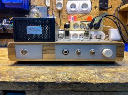
Hello to all enthusiasts of home tube designs! I come today with a headphone amplifier project using ECC88 and 6N6P tubes. This amplifier was created to drive the Beyerdynamic DT990 Pro headphones, which, as befits studio headphones, have a sizable impedance (250 Ω). It was one of the longer projects, due to the fact that I am still a beginner when it comes to electronics, and also because I was implementing solutions that were completely new to me at the time. It is not a perfect design, and unfortunately it is not universal either, because the impedance that this amplifier can handle should not be lower than 250 Ω (due to the design of the output stage), but for my applications it is ideal.
I built the amplifier using components I had in store, i.e. transformer, tubes (although initially there was going to be a second 6N6P or 6N1P in the control stage, but I got a couple of ECC88s from a friend). As the power transformer had limited capabilities (200 V AC and 100 mA), it fell to a 'simple' cathode secondary for the output. Had I had a transformer with higher maximum currents and voltages, I probably would have opted for a White's secondary, but alas .
.
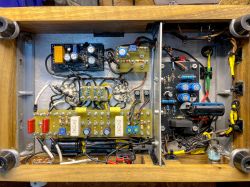
There was a lot of news in the power supply, as I decided to implement active filtering with a gyrator (which in the end was not particularly necessary) and a capacitance multiplier. The control stage on the ECC88 is a typical circuit, without any miracles, except that it has a balance potentiometer in the cathodes of both tubes (not the best solution, but it works). Much more (in my opinion) happens in the final stage. The 6N6P tube acts as a cathode secondary, however it is not a typical secondary as the cathode resistor has been replaced by a current source on an NPN MJE340 transistor (now I would do it on a MOSFET). The current sources are powered by a separate power supply with a built-in base voltage turn-on delay (set to 15 seconds from what I remember). Each source has a precision potentiometer in the emitter to set the current, so that the current of both halves of the tube can be set perfectly. Because the voltage at the 6N6P cathodes exceeds the maximum heater-cathode voltage, I used an elevation voltage that is 40 V. I took a lot of information and inspiration from Mr Merlin Blencowe's books. I attached the MJE340s to the chassis because they heat up a lot, and that's why the name "FARELKA" came about, because the amplifier can get (but of course within the norm).
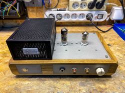
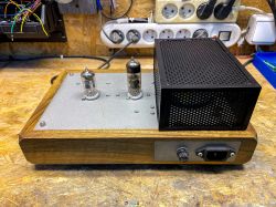
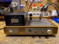
I made the enclosure from walnut wood and aluminium, which I cut out using CNC. The screw mounts, the transformer 'cage' and some other parts were printed on a 3D printer. I placed the amplifier parts on a turret board, as I am a fan of this technique. I have tried to keep the interior as neat as possible, but that is for you to judge. I like it.
As for the sound - in my opinion it sounds brilliant. You can't hear any noises (when I first fired it up during testing and heard nothing in the headphones, I was sure it wasn't working. All I had to do was turn up the volume control). I'm not an audiophile or anything like that, but the amplifier continues to impress me, as well as my friends who have had the opportunity to test it.
What do you guys think? ;D
 .
.
 .
.
 .
.
I built the amplifier using components I had in store, i.e. transformer, tubes (although initially there was going to be a second 6N6P or 6N1P in the control stage, but I got a couple of ECC88s from a friend). As the power transformer had limited capabilities (200 V AC and 100 mA), it fell to a 'simple' cathode secondary for the output. Had I had a transformer with higher maximum currents and voltages, I probably would have opted for a White's secondary, but alas
There was a lot of news in the power supply, as I decided to implement active filtering with a gyrator (which in the end was not particularly necessary) and a capacitance multiplier. The control stage on the ECC88 is a typical circuit, without any miracles, except that it has a balance potentiometer in the cathodes of both tubes (not the best solution, but it works). Much more (in my opinion) happens in the final stage. The 6N6P tube acts as a cathode secondary, however it is not a typical secondary as the cathode resistor has been replaced by a current source on an NPN MJE340 transistor (now I would do it on a MOSFET). The current sources are powered by a separate power supply with a built-in base voltage turn-on delay (set to 15 seconds from what I remember). Each source has a precision potentiometer in the emitter to set the current, so that the current of both halves of the tube can be set perfectly. Because the voltage at the 6N6P cathodes exceeds the maximum heater-cathode voltage, I used an elevation voltage that is 40 V. I took a lot of information and inspiration from Mr Merlin Blencowe's books. I attached the MJE340s to the chassis because they heat up a lot, and that's why the name "FARELKA" came about, because the amplifier can get
I made the enclosure from walnut wood and aluminium, which I cut out using CNC. The screw mounts, the transformer 'cage' and some other parts were printed on a 3D printer. I placed the amplifier parts on a turret board, as I am a fan of this technique. I have tried to keep the interior as neat as possible, but that is for you to judge. I like it.
As for the sound - in my opinion it sounds brilliant. You can't hear any noises (when I first fired it up during testing and heard nothing in the headphones, I was sure it wasn't working. All I had to do was turn up the volume control). I'm not an audiophile or anything like that, but the amplifier continues to impress me, as well as my friends who have had the opportunity to test it.
What do you guys think? ;D
 .
.


 .
.
 .
.
Cool? Ranking DIY


