 .
.
I have been looking for something like this for a long time - here is a 'smart' light switch that is not touch-sensitive. Instead, it offers classic "clicking" buttons based on microswitches. In addition, the whole thing is based on a module from BK7231, which means you can change the software and fire this switch 100% locally, or even pair it with Home Assistant.
The switch range shown here includes single, double and triple versions. They are available in two colours. They can be searched by model name: Milfra TB11, TB12 or TB13. If it changes, you can look visually by the pictures, because this product just stands out a bit.
 .
.
We pay around £70 per piece, depending on where we buy and which version we choose.
We receive a box like this:


 .
.
There is also a capacitor and mounting screws inside.

N connection is optional:
 .
.
Instructions:


But I'll skip the pairing with the manufacturer's cloud here, I've discussed it many times, so it's time to look inside.
Interior of TB13 .
We remove the frame and then the front:


 .
.
Three beautiful microswitches, a rare sight in this type of product. I also see a Wi-Fi module...


 .
.
Interestingly, the PCB provides for two button spacings.
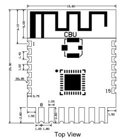
However, let's focus on the Wi-Fi, there's a CBU inside, the BK7231N:
 .
.
| Pin number | Symbol | I/O type | Function | Function | |
| 1 | 1 | P14 | I/O | Common GPIO, which can be reused as SPI_SCK (Correspond to Pin 11 of the IC) | |
| 2 | P16 | I/O | .Common GPIO, which can be reused as SPI_MOSI (Correspond to Pin 12 of the IC) | ||
| 3 | P20 | I/O | Common GPIO (Correspond to Pin 20 of the IC) | ||
| 4 | P22 | I/O | Common GPIO (Correspond to Pin 18 of the IC) | ||
| 5 | ADC | I/O | ADC, which corresponds to P23 on the internal IC (Correspond to Pin 17 of the IC) | ||
| 6 | RX2 | I/O | UART_RX2, which corresponds to P1 on the internal IC. (Correspond to Pin 28 of the IC) | ||
| 7 | TX2 | I/O | UART_TX2, which is used for outputting logs and corresponds to P0 of the internal IC (Correspond to Pin 29 of the IC) | ||
| 8 | P8 | P8I/O | Support hardware PWM (Correspond to Pin 24 of the IC) | ||
| 9 | P7 | I/O | Support hardware PWM (Correspond to Pin 23 of the IC) | ||
| 10 | 10P6 | I/O | Support hardware PWM (Correspond to Pin 22 of the IC) | ||
| 11 | P26 | I/O | Support hardware PWM (Correspond to Pin 15 of the IC) | ||
| 12 | P24 | I/O | Support hardware PWM (Correspond to Pin 16 of the IC) | ||
| 13 | GND | P | Power supply reference ground | ||
| 14 | 3V3 | P | Power supply 3V3 | ||
| 15 | TX1 | I/O | UART_TX1, which is used for transmitting user data and corresponds to Pin 27 of the IC. For the MCU solution, please refer to CBx Module. | ||
| 16 | .RX1 | I/O | UART_RX1, which is used for receiving user data and corresponds to Pin 26 of the IC. For the MCU solution, please refer to CBx Module. | ||
| 17 | P28 | I/O | Common GPIO (Correspond to Pin 10 of the IC) | ||
| 18 | .CEN | I/O | Reset pin, low active (internally pulled high), compatible with other modules (Correspond to Pin 21 of the IC) | ||
| 19 | P9 | I/O | Common GPIO (Correspond to Pin 25 of the IC) | ||
| 20 | P17 | I/O | Common GPIO, which can be reused as SPI_MISO (Correspond to Pin 14 of the IC) | ||
| 21 | P15 | I/O | Common GPIO, which can be reused as SPI_CS (Correspond to Pin 13 of the IC) | ||
| Test point point | CSN | I/O | Mode selection pin. If it is connected to the ground before being powered on, enter the firmware test mode. If it is not connected or connected to VCC before being powered on, enter the firmware application mode. Correspond to Pin 19 on the internal IC. |
Looking further afield - I can't see anything significant on the other side of the PCB:
ADVERTISEMENT
 .
.
What's left is the board with the relays and power supply:

 .
.
There is no LDO AMS1117-3.3 V here. This U2 circuit next to coil L6 is probably a step down providing 3.3 V instead of an LDO. Its designation is ADJN. In addition to this, I see an interesting AGM303A, which appears to be a fairly powerful surface-mount MOSFET transistor. He is probably used for no-neutral operation.


 .
.
At the top of the board you can also see the S7132B inverter controller, this time it is not an unisolated step down, but probably a flyback nonetheless:
 .
.
 .
.
I also noticed the rather large capacitance of the electrolytic capacitors on board. This is probably because this device can operate in no-neutral mode:

Programming .
You need to solder the four wires to the CBU pins, according to the flasher's instructions:
https://github.com/openshwprojects/BK7231GUIFlashTool
You can also follow our video:
In my case it worked out like this:

Flasher correctly recognises the configurations:
 .
.
Batch copy:
https://github.com/openshwprojects/FlashDumps/commit/1ec19ea303fd436fc4dd2e0bbe9764e3b3054fab
JSON Tuya:
Code: JSON
Verbal description:
Device configuration, as extracted from Tuya:
- Button (channel 1) on P7
- Relay (channel 3) on P20
- WiFi LED on P24
- Button (channel 3) on P28
- Relay (channel 2) on P16
- Button (channel 2) on P8
- Relay (channel 1) on P14
Device seems to be using CBU module, which is using BK7231N.
And the Tuya section starts, as usual, at 2023424
OBK template:
Code: JSON
The template should be imported according to:
Then you can link to HA:
Summary .
Why aren't there more products like this? I much prefer the "clicky" buttons to the touchscreen ones. And also after changing the firmware, the classic ones can be better used, because you can script for them separately the events of long press, single click or there double click, details here . For example, it can be made that a triple click turns on not this one light, but all the lights in the room (also LED strips, etc). With Home Assistant and open software, the possibilities are really great.
I am very happy with the finding shown here.
And what do you guys think? Better such a switch or a touchscreen one? .
Cool? Ranking DIY Helpful post? Buy me a coffee.


