logo elektroda
logo elektroda
X
logo elektroda

YOMOGI YO-WIFI-C02 Smart Curtain with RF remote - Working progress

iz1gww 393 9
ADVERTISEMENT
  • Helpful post
    #1 21637839
    iz1gww
    Level 11  
    Hi guys, i disassembled a smart curtain switch mod. YO-WIFI-C02 branded YOMOGI
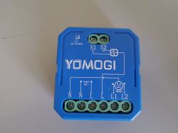
    Blue YOMOGI YO-WIFI-C02 module with labeled terminals and connection diagram.YO-WIFI-C02 module in blue casing with technical specifications

    inside


    Circuit board of curtain controller module labeled QL-0870 Rev:A, dated 2024.03.30 Electronic module with two relays and screw terminals on a PCB

    inside i have found a W701 mcu, searching info online i understand that is a RTL8720 clone (or compatible)


    Electronic board with W701 chip, top view of populated white PCB Electronics module PCB with labeled pins TXD, A19, A18, A0, A16, A15


    Photo showing both sides of W701 module with labeled GPIO pins and connections


    than there is a custom rf receiver for remote(i suppose on 2.4Ghz band due to the 16Mhz quartz)

    RF module with VCC and NC pins labeled, showing IC chip and antenna

    QL-0866 module with labeled GND and GPIO (TX & BINDING) pins

    and relative remote

    White remote with six buttons for curtain control and position percentages

    with the same custom IC

    RF remote circuit board with labeled buttons and central chip visible

    Close-up of PCB with 2148aMC chip and 16 MHz crystal oscillator

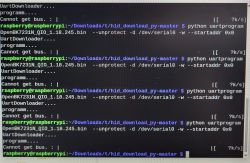
    for programming i use the classic tools and gear : usb to ttl adapter with 3.3v supply and amebaZII PGTool 1.2.47, with OpenRTL87X0C_1.18.155.bin

    connected in this way :

    W701 Module         USB-TTL Module
    VCC                                3.3v
    GND                               GND
    A15       TX
    A16                                 RX
    A0                                   3.3v           (for bootloader mode)
    RXD                                3.3v           (for bootloader mode)

    all flashing procedure completed correctly and i can proceed with configuration


    PIN A07           -             Button 2  Open
    PIN A11           -             LED
    PIN A12           -             Button Close
    PIN A13           -             Data from remote receiver
    PIN A18           -             Relays 1  Close
    PIN A19           -             Relays 2 Open

    here my autoexec script

    Code: Text
    Log in, to see the code

    at this point i have a smart curtain module basically working, but without remote function.... i enable the driver tuyaMCU and i see that the custom mcu use a protocol different from the classic tuyaMCU, it use only 3 byte at all and the 2 header byte are 55 A5 insteath classic 55 AA so the tuyaMCU driver can't work... i collect the codes of all remote's function and they are

    Code: Text
    Log in, to see the code


    now i'm stuck, i don't find any function to use with the script for manage this code, i don't find a function that permit to read the bytes read by a gpio...
    any suggestion?

    thank you very mutch
    Alex
  • ADVERTISEMENT
  • #2 21638242
    divadiow
    Level 36  
    interesting. not seen an AmebaZ2 on that format module before.

    Did you capture boot log from TX?
  • #3 21638541
    iz1gww
    Level 11  
    >>21638242

    Hi, divadiow, I'm sorry not... I have done the dump but the utility didn't recognize any Tuya info about pin and functions...
    Bye
    Alex
  • ADVERTISEMENT
  • #4 21638583
    divadiow
    Level 36  
    boot log from your backup:

    Code: Text
    Log in, to see the code


    Added after 5 [hours] 12 [minutes]:

    I wonder if this can be used to receive bytes from IO14

    insmod wrote:
    Managed to create a uart->tcp bridge driver.
    Looks like it works.


    Quote:
    startdriver uarttcp 115200 512 1 1
    - https://www.elektroda.com/rtvforum/topic4130211.html
  • ADVERTISEMENT
  • #5 21638896
    iz1gww
    Level 11  
    >>21638583
    thanks for the tip but no result... the speed is 9600 so I try
    9600 512 1 1
    9600 512 0 1
    9600 512 0 0
    9600 512 1 0

    but no one on log output...
    Alex
  • ADVERTISEMENT
  • #7 21638912
    iz1gww
    Level 11  
    >>21638900
    i review the original message because i found there is a mismatch in pin definition, is pin 13 connect to custom MCU and not 14, i correct the post...
    sorry
    Alex

    Added after 4 [minutes]:

    A driver that redirects packets coming from a selectable UART (or better yet, GPIO) and allows for a script-level comparison would be sufficient...
    In the meantime, I'm looking at the C++ code source from the tuyamcu driver to re-create a stripped-down version for this purpose...

    Added after 42 [minutes]:

    here a code draft, but i need documentation about how link output on channel entity of openbeken...

    
    #include "../new_common.h"
    #include "../new_pins.h"
    #include "../new_cfg.h"
    // Commands register, execution API and cmd tokenizer
    #include "../cmnds/cmd_public.h"
    #include "../mqtt/new_mqtt.h"
    #include "../logging/logging.h"
    #include "../hal/hal_pins.h"
    #include "drv_public.h"
    #include "drv_local.h"
    #include "drv_uart.h"
    #include "../httpserver/new_http.h"
    
    #define RF2148_CMD_75P    0x02
    #define RF2148_CMD_50P    0x03
    #define RF2148_CMD_25P    0x04
    #define RF2148_CMD_DOWN   0x07
    #define RF2148_CMD_UP     0x09
    #define RF2148_CMD_STOP   0x0A
    #define RFRemote2148AMC_PACKET_SIZE (3)
    
    
    const char* RFRemote2148AMc_GetCmdTypeString(int codeByte) {
       if (codeByte == RF2148_CMD_75P)
      {
        addLogAdv(LOG_INFO, LOG_FEATURE_RFREMOTE2148AMC, "ProcessIncoming: 75% command received.\n");
        return "75P";
      }
       else if (codeByte == RF2148_CMD_50P)
      {
        addLogAdv(LOG_INFO, LOG_FEATURE_RFREMOTE2148AMC, "ProcessIncoming: 50% command received.\n");
        return "50P";
      }
       else if (codeByte == RF2148_CMD_25P)
      {
        addLogAdv(LOG_INFO, LOG_FEATURE_RFREMOTE2148AMC, "ProcessIncoming: 25% command received.\n");
        return "25P";
      }
      else if (codeByte == RF2148_CMD_DOWN)
      {
          addLogAdv(LOG_INFO, LOG_FEATURE_RFREMOTE2148AMC, "ProcessIncoming: DOWN command received.\n");
        return "DWN";
      }
       else if (codeByte == RF2148_CMD_UP)
      {
        addLogAdv(LOG_INFO, LOG_FEATURE_RFREMOTE2148AMC, "ProcessIncoming: UP command received.\n");
        return "UP";
      }
       else if (codeByte == RF2148_CMD_STOP)
      {
          addLogAdv(LOG_INFO, LOG_FEATURE_RFREMOTE2148AMC, "ProcessIncoming: STOP command received.\n");
        return "STP";
      }
      else
      {
        addLogAdv(LOG_INFO, LOG_FEATURE_RFREMOTE2148AMC, "%s is not a valid codes command\n", codeByte);
        return "UNK";
      }
       
    }
    
    void RFRemote2148AMc_Init() {
      UART_InitUART(g_baudRate, 0, false);
      UART_InitReceiveRingBuffer(1024);
    }
    
    void RFRemote2148AMc_OnEverySecond() {
    
    }
    void RFRemote2148AMc_AppendInformationToHTTPIndexPage(http_request_t* request) {
      hprintf255(request, "<h4>RF Remote 2148Amc is running!</h4>");
    
    }
    void RFRemote2148AMc_QuickTick() {
    
    }
    void RFRemote2148AMc_StopDriver() {
    
    }
    
    void RFRemote2148AMc_ProcessIncoming(const byte* data, int len)
    {
     if (sizeof(data) !=3)
     {
          addLogAdv(LOG_INFO, LOG_FEATURE_RFREMOTE2148AMC, "ProcessIncoming: packet data size is different from 3 bytes\n");
          return;
     }
     if (data[0] != 0x55 || data[1] != 0xA5) {
          addLogAdv(LOG_INFO, LOG_FEATURE_RFREMOTE2148AMC, "ProcessIncoming: header bytes values not correct %s\n", data);
          return;
       } 
    
      return RFRemote2148AMc_GetCmdTypeString(data[2]);
      
    }


    void RFRemote2148AMc_PrintPacket(byte *data, int len) {
       int i;
       char buffer_for_log[256];
       char buffer2[4];
       
             buffer_for_log[0] = 0;
             for (i = 0; i < len; i++) {
                snprintf(buffer2, sizeof(buffer2), "%02X ", data[i]);
                strcat_safe(buffer_for_log, buffer2, sizeof(buffer_for_log));
             }
             addLogAdv(LOG_INFO, LOG_FEATURE_RFREMOTE2148AMC, "Received: %s\n", buffer_for_log);
    #if 1
             // redo sprintf without spaces
             buffer_for_log[0] = 0;
             for (i = 0; i < len; i++) {
                snprintf(buffer2, sizeof(buffer2), "%02X", data[i]);
                strcat_safe(buffer_for_log, buffer2, sizeof(buffer_for_log));
             }
             // fire string event, as we already have it sprintfed
             // This is so we can have event handlers that fire
             // when an UART string is received...
             EventHandlers_FireEvent_String(CMD_EVENT_ON_UART, buffer_for_log);
    #endif
    }
    
    void RFRemote2148AMc_RunReceive() {
       byte data[192];
       int len;
       while (1)
       {
          len = UART_TryToGetNextTuyaPacket(data, sizeof(data));
          if (len > 0) {
             RFRemote2148AMc_PrintPacket(data,len);
             RFRemote2148AMc_ProcessIncoming(data, len);
          }
          else {
             break;
          }
       }
    }
    
    commandResult_t RFRemote2148AMc_SetBaudRate(const void* context, const char* cmd, const char* args, int cmdFlags) {
       Tokenizer_TokenizeString(args, 0);
       // following check must be done after 'Tokenizer_TokenizeString',
       // so we know arguments count in Tokenizer. 'cmd' argument is
       // only for warning display
       if (Tokenizer_CheckArgsCountAndPrintWarning(cmd, 1)) {
          return CMD_RES_NOT_ENOUGH_ARGUMENTS;
       }
    
       g_baudRate = Tokenizer_GetArgInteger(0);
       UART_InitUART(g_baudRate, 0, false);
    
       return CMD_RES_OK;
    }
  • #8 21639009
    insmod
    Level 29  
    PA13 is default for UART0. So, if secondary UART is not enabled in flags, it will be used as RX.
    UartTCP driver has logging disabled. The only way for it to be used here, is to simulate device on PC with something like a python program.
    If UTCP_DEBUG is defined in build, then what is received by module can be viewed in log with UartTCP driver enabled.
  • #9 21639026
    iz1gww
    Level 11  
    >>21639009
    I think at this point that the only way to get module fully functional is to write a specific driver to this purpose...

    Alex
  • #10 21651441
    iz1gww
    Level 11  
    Where, if it's possible, I can place the request for driver creation?
    Thank you

Topic summary

A YOMOGI YO-WIFI-C02 smart curtain switch was disassembled revealing internal components including a W701 microcontroller unit (MCU), identified as a clone or compatible version of the Realtek RTL8720. The device features a custom RF receiver, likely operating in the 2.4 GHz band, inferred from the presence of a 16 MHz quartz crystal. The discussion includes photographic documentation of the module and its internal circuitry. A response noted the unusual module format resembling an AmebaZ2 and inquired about capturing the boot log via TX for further analysis.
Summary generated by the language model.
ADVERTISEMENT