 .
.
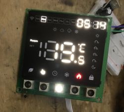
I will present here a surface-mounted thermostat with LCD, external sensor and WiFi-based wireless control. The product shown here is compatible with the Tuya app and has a 5+2/6+1 programming function that allows you to set up to 6 different temperature settings for each day of the week and an additional setting for the weekend.
I will also include its communication analysis in the theme, which will allow me to change its firmware and upload OpenBeken so that it can be cloud free and connected to Home Assistant.
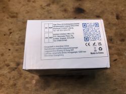
We bought the thermostat for £140. Let's start with the contents of the kit.

 .
.
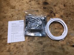
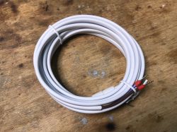
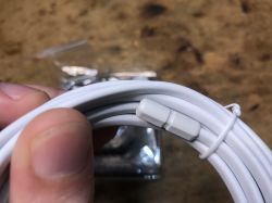
The unit, probe and instructions are included.
 .
.
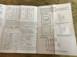
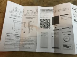
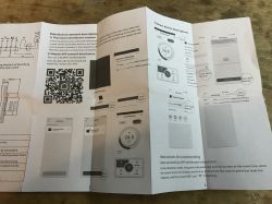
Images of the English-language manual:

 .
.
 .
.
It's rather pointless to rewrite and repost the instructions here, so we'll get straight to the post-pairing application presentation.
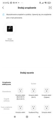
Pairing goes without a hitch - the device is based on the BK7231, so it is already detected over Bluetooth:
 .
.
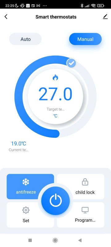
The device panel is quite complex. We have here mainly two modes of operation:
- automatic (according to a programme)
- manual (we set the temperature ourselves at a given moment)
We also have options such as child lock, which allows the touch panel of the appliance to be deactivated.
 .
.
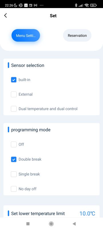
There is also an antifreeze option, which automatically starts heating when the temperature is far too low.
 .
.
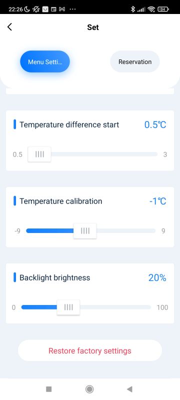
In the settings there is a choice of programme and probe - it can be external or internal.
 .
.
Probe calibration is also available and there is even an option to control the backlight level.
 .
.
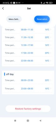
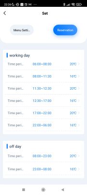
The creation of the programme itself is quite simple. We select the periods and temperatures.
 .
.
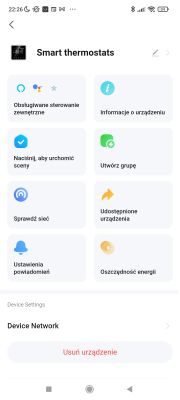
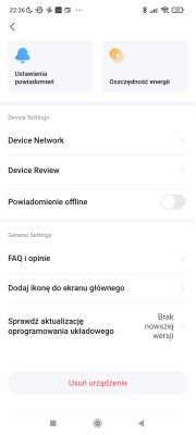
The rest of the options do not stand out - as we usually have the option of sharing a device, for example.
Now it's time for the more interesting bit....
Interior of the device .
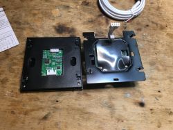
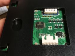
The device is built like a typical WiFi controlled light switch. We remove the front panel.
 .
.
You can already see some of the electronics, but here, however, there is an additional plastic component inside. More needs to be removed.

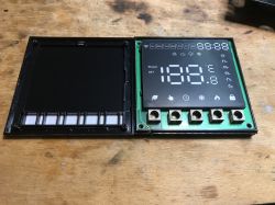 .
.
It appears that there is no LCD here after all. The screen is based on LEDs. The seller has provided information that is not true.
 .
.
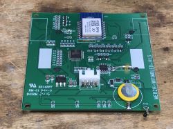
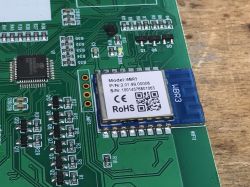
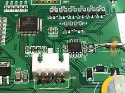
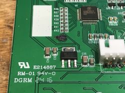
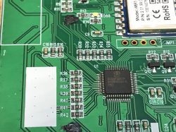
The main PCB is marked ME82H-WIFIMBLED-V1.3 The device is based on the WiFi WBR3 module , a chip from Realtek. In addition to the WiFi module, we also have an additional microcontroller which takes care of all the logic of the device, and a timer chip real DS1302Z with a quartz clock resonator and power supply backup for times of power loss. This allows the device to resume programming even if it loses power completely and WiFi is not available to retrieve time from the Internet with the NTP service.
 .
.
The main MCU is the SOC SC92F8547P. It communicates with the WiFi module via the TuyaMCU protocol:
TuyaMCU protocol - communication between microcontroller and WiFi module .
This means that it will be useful to capture packets on the UART line right away. This will allow us to determine the dpIDs (identifiers) of the variables that determine the operation of the thermostat.
What remains is the board with the power supply and relays - ME86-DY-1.4.
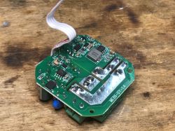
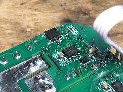 .
.
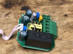
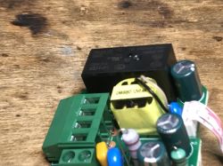
The power supply in the device is implemented based on the LNK606DG.
 .
.
The GMF2A is probably an inverter. Presumably the power supply gives 12V and something else has to generate 5V for the second board.
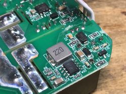
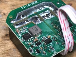 .
.
The presence of a large 12V relay (HF115F) confirms my suspicions. What we have here is a separate 12V power supply and separately some sort of step down converter. I don't think this 12V is going directly to the AMS1117-3.3V.
 .
.
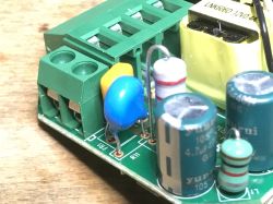
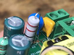
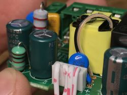
The board is quite well built. A varistor is present at the input to protect against surges, and there is also an anti-interference capacitor.
 .
.
<br> UART communication analysis .
In this section I assume familiarity with TuyaMCU. I have described it here:
TuyaMCU protocol - communication between microcontroller and WiFi module .
For this, my tool for its analysis is still useful:
TuyaMCU Analyzer - UART packet decoder for Tuya devices - dpID detector .
Packet capture must be done in a secure manner. The device may have a mains potential on it, so you either need to supply it from a safe power supply (some devices of this type will work when run with a 24V DC power supply, for example) or use isolators such as ADUM1201. Otherwise we can short circuit the mains potential from the device to our USB to UART converter and damage the computer.
Here are the more interesting of the collected packages. Each one represents a different action performed by the applications.
Shutdown by phone:
Received by WiFi module:
55 AA	00	06		00 05	0101000100	0D
HEADER	VER=00	SetDP		LEN	dpId=1 Bool V=0		CHK

Received by WiFi module:
55 AA	00	00		00 00		FF
HEADER	VER=00	Heartbeat		LEN		CHK

Received by WiFi module:
55 AA	00	1C		00 08	01180B0A161C3907	C3
HEADER	VER=00	Date		LEN	bOk=1 24/11/10 22:28:57	CHK

Received by WiFi module:
55 AA	00	20		00 02	0100	22
HEADER	VER=00	Unk		LEN	0100	CHK

Received by WiFi module:
55 AA	00	00		00 00		FF
HEADER	VER=00	Heartbeat		LEN		CHK
The phone sends a change of state from dpID 1 to 0, type is boolean.
On:
Received by WiFi module:
55 AA	00	06		00 05	0101000101	0E
HEADER	VER=00	SetDP		LEN	dpId=1 Bool V=1		CHK
Similarly, the state changes to 1.
Disabling child lock:
Received by WiFi module:
55 AA	00	06		00 05	2801000100	34
HEADER	VER=00	SetDP		LEN	dpId=40 Bool V=0		CHK
Child lock to dpID 40, bool type.
Setting the target temperature to 26.5:
Received by WiFi module:
55 AA	00	06		00 08	1002000400000109	2D
HEADER	VER=00	SetDP		LEN	dpId=16 Val V=265		CHK

Received by WiFi module:
55 AA	00	00		00 00		FF
HEADER	VER=00	Heartbeat		LEN		CHK

Received by WiFi module:
55 AA	00	1C		00 08	01180B0A161E1B07	A7
HEADER	VER=00	Date		LEN	bOk=1 24/11/10 22:30:27	CHK

Received by WiFi module:
55 AA	00	20		00 02	0100	22
HEADER	VER=00	Unk		LEN	0100	CHK
dpID 16 is the temperature, sent as an integer type, multiplied by 10.
Change of sensor to external:
Received by WiFi module:
55 AA	00	00		00 00		FF
HEADER	VER=00	Heartbeat		LEN		CHK

Received by WiFi module:
55 AA	00	1C		00 08	01180B0A161E3907	C5
HEADER	VER=00	Date		LEN	bOk=1 24/11/10 22:30:57	CHK

Received by WiFi module:
55 AA	00	20		00 02	0100	22
HEADER	VER=00	Unk		LEN	0100	CHK

Received by WiFi module:
55 AA	00	06		00 05	2B04000101	3B
HEADER	VER=00	SetDP		LEN	dpId=43 Enum V=1		CHK
dpId 43 is an enumeration, a value of 1 indicates external.
Change the lower temperature limit to 12:
Received by WiFi module:
55 AA	00	06		00 08	1A02000400000078	A5
HEADER	VER=00	SetDP		LEN	dpId=26 Val V=120		CHK
Same as with target temperature, value multiplied by 10.
Upper limit at 55:
Received by WiFi module:
55 AA	00	06		00 08	1302000400000226	4E
HEADER	VER=00	SetDP		LEN	dpId=19 Val V=550		CHK
Change difference start to 1:
Received by WiFi module:
55 AA	00	06		00 08	6A0200040000000A	87
HEADER	VER=00	SetDP		LEN	dpId=106 Val V=10		CHK
Calibration to -7:
Received by WiFi module:
55 AA	00	06		00 08	1B020004FFFFFFF9	24
HEADER	VER=00	SetDP		LEN	dpId=27 Val V=-7		CHK
This is interesting, the calibration does not allow decimals.
Backlighting at 50%:
\Received by WiFi module:
55 AA	00	1C		00 08	01180B0A16263707	CB
HEADER	VER=00	Date		LEN	bOk=1 24/11/10 22:38:55	CHK

Received by WiFi module:
55 AA	00	20		00 02	0100	22
HEADER	VER=00	Unk		LEN	0100	CHK

Received by WiFi module:
55 AA	00	06		00 05	3404000102	45
HEADER	VER=00	SetDP		LEN	dpId=52 Enum V=2		CHK
Curious, unknown packet type 0x20?
Change working day of the programme:
\
Received by WiFi module:
55 AA	00	1C		00 08	01180B0A16271907	AE
HEADER	VER=00	Date		LEN	bOk=1 24/11/10 22:39:25	CHK

Received by WiFi module:
55 AA	00	20		00 02	0100	22
HEADER	VER=00	Unk		LEN	0100	CHK

Received by WiFi module:
55 AA	00	00		00 00		FF
HEADER	VER=00	Heartbeat		LEN		CHK

Received by WiFi module:
55 AA	00	06		00 1C	6C00001806001E0800100B1E140C1E10110014160010080014170010	E6
HEADER	VER=00	SetDP		LEN	dpId=108 Raw V=06 00 1E 08 00 10 0B 1E 14 0C 1E 10 11 00 14 16 00 10 08 00 14 17 00 10		CHK
Change of mode to auto:
Received by WiFi module:
55 AA	00	06		00 05	0204000100	11
HEADER	VER=00	SetDP		LEN	dpId=2 Enum V=0		CHK
Further steps .
We have already gathered the information needed to change the firmware. There are now two further steps to follow, the first is to upload the new firmware via the UART. Instructions below:
WBR2, WBR3, WBRU, W701-VA2-CG pinout, datasheet, flashing for Home Assistant .
The second is the TuyaMCU configuration:
TuyaMCU flashing, installation and configuration guide - configure dpID for Home Assistant .
I will address this in a separate section.
Summary .
The product shown here is quite advanced, allowing manual or automatic control of the heating and also giving additional options such as calibration, child lock or there backlight level adjustment. The LED display seems quite clear to me, and I have no complaints about the touch functions either.
The internal design of the product is slightly better than usual. This time the manufacturer did not forget the varistor, the anti-interference capacitor is also present. The logic is based on TuyaMCU, which I have already discussed separately on the forum.
The WiFi module used inside is based on a Realtek chip, which is already supported by OpenBeken . It should be easy to change the firmware, which I will show in the next section.
Do you use this type of thermostat? Feel free to comment.
Cool? Ranking DIY Helpful post? Buy me a coffee.


