 Added after 9 [minutes]:
 Hello
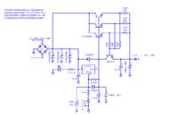
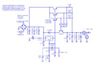
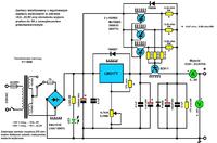
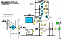
In the attached drawing I present a simple power supply with adjustable output voltage in the range of 0V ... 25V with regulation of output current limitation in the range of 1.5 ... 10A and with short-circuit protection.
The PSU is protected against polarity reversal at the PSU output sockets thanks to the D22-20-04 diode (20A / 400V or higher current) connected to the PSU output, e.g. by incorrectly connecting a different voltage source to the output sockets. It's not a perfect solution, but it does the job.
The presented power supply, after correct assembly according to the diagram and commissioning, does not require any adjustment and is immediately ready for operation.
The basic element in the power supply is the LM317T voltage stabilizer in the TO-220 housing, while the stabilizing elements connected in series with the input voltage and the load are five appropriately connected bipolar NPN power transistors BD911 and BD249C.
The BD911 transistor drives four BD249C transistors connected in parallel, thus creating a complex power control transistor operating in the Darlington circuit. The base of the BD911 transistor is connected directly to the Vout pin of the LM317T stabilizer, where the transistor is pre-current controlled. This current is sufficient to drive the power control transistor and therefore it is possible to load the power supply output with a current of up to 10A without any problems.
Changing the voltage at the Vout pin of the LM317T stabilizer from + 1.25V to + 26.25V causes the voltage at the output of the power supply to change from 0V to + 25V, because the combined power control transistor works in the Darlington circuit.
The output voltage is regulated by a 4.7k / A-0.25W linear potentiometer. A 33k resistor connected in parallel to a 4.7k / A potentiometer sets the maximum output voltage of + 25V. By changing the value of this resistor, the upper range of the output voltage can be changed.
The base-emitter junctions of the BD249C transistors, 0.39 Ohm / 5W resistors and the BD911 transistor with a 470 Ohm / A potentiometer are involved in the short-circuit protection and current limit control system.
A 470 Ohm / A-0.25W linear potentiometer is used to adjust the current limitation.
The effectiveness of the minimum and maximum current limiting control depends on the size of the output voltage and, of course, on the setting of the 470 Ohm / A-0.25W potentiometer slider.
At the minimum output voltage, regulation of the output current limitation is performed with a full (100%) turn of the potentiometer knob. On the other hand, at the maximum output voltage, current limiting is performed in the half (50%) of the potentiometer knob turn.
When the potentiometer slider is set at a 47 Ohm resistor, the power supply output can be loaded only with the minimum current, when the potentiometer slider is set at a 4.7 k resistor, the power supply output can be loaded with the maximum current.
If the minimum voltage is set at the output of the power supply, and the load current is maximum, the potentiometer slider should be set at the end of the resistance path, i.e. closer to the 4.7k resistor. If the maximum voltage is set at the output of the power supply and the load current will also be setmaximum, the potentiometer slider should be set in the middle of the potentiometer resistance path.
The BD249C power transistors should be placed on a large ribbed heat sink. The BD911 transistor controlling the BD249C transistors and the LM317T stabilizer should be placed on small separate heat sinks.
BD249C transistors after the heat sink require additional cooling with forced air circulation by means of fans attached to the heat sink.
To reduce the power of losses of BD249C transistors in the power supply, a network transformer with a power of P = 300W with two secondary windings 2 x 13 ... 14VAC / 10A connected in series was used, which are properly switched depending on the voltage that occurs at the output of the power supply, as a result of reducing or they increase the input voltage at the collectors of BD249C transistors.
Remember to use a soft-start system in this power supply.
The power supply uses analog panel meters which, when connected at the output of the power supply, act as an ammeter and voltmeter used to determine changes in current and voltage.
greetings
Added after 1 [hours] 4 [minutes]: A small addition, the two BD911 transistors used in the power supply should be placed on small separate heat sinks.


