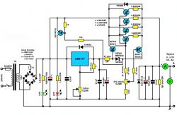
I have a question for the gentlemen who assembled and launched Mr. Krzysztof's power supply. Which of the available schematics has all the corrections applied? How is this power supply for you? Has anyone been using the maximum current for a long time?
The revised power supply schematic (only one resistor was missing) and revised PCBs can be found in post # 82. Please see the topic "Why the lm317t power supply does not work" in the "Electronic beginners" section The power supply can be loaded with maximum current for a long time, but the power transistors should be placed on a large, ribbed heat sink with additional cooling by fans. Here are the opinions about the current efficiency of the power supply.
tomasz.laskowski5 wrote:
The power supply works, the voltage regulation is ok ... The power supply was loaded with 3.5A and 7.2A current.
laciaty1981 wrote:
To load the system, I used two h4 bulbs connected in parallel and set the voltage to 12V, the current consumption is about 8A.
mayzel wrote:
calmly works with my VHF radio, where transmitting is up to 8A power consumption at 25W.
laciaty1981 wrote:
Hello, after a long break. Finally, I found time to take care of the power supply and made corrections according to Mr. Krzysztof.
The power supply works !!!
Robcio_K wrote:
Second question: I have a 400 Ohm potentiometer on hand, which I am going to use to regulate the current. How much will the regulation range suffer from the lack of these 70 ohms?
Such a potentiometer can be used. At lower voltages, the current regulation range will slightly decrease.
Thank you for your response. I put this power supply on a board I designed and started it on Monday, I must admit that it works very well, it regulates both current and voltage correctly. I have not checked the current efficiency yet, because when starting the system it was powered from a laboratory power supply with a maximum current of 2A. The system started working the first time. In the near future, I will install the system with the target transformer and then test how it behaves in the full range of currents.
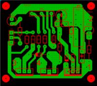
@mayzel I attach the view of the tiles below. There are no elements connected in the diagram directly to the power supply output, i.e. diode D22-20-04 and elements parallel to it. They will be connected directly to the power supply output from the inside. The tile is quite compact, its dimensions are 50 x 45 mm. When designing the board, I assumed that there is no point in running current paths through it, since the power transistors are in the TO-3 housing and I will have to connect the current connections to them anyway. That's why I made a separate PCB for them, mounted on the heat sinks from the bottom of the transistors. In addition to the KD502 soldered to it, there are equalizing resistors and the P600M diode on it. Thick wires will be connected to this PCB, the control system itself is connected to ordinary, thin wires. Due to the fact that in my application this system will work as a rectifier, a precision potentiometer is used for voltage regulation, which will not be available after closing the housing. On the other hand, the current adjustment potentiometer will be connected on short wires. The whole thing will be closed in a housing made of an old UPS. The markings of the elements are my creativity. The layout is so simple that there should be no problems with figuring out which element on the board corresponds to the element in the diagram. Marking of the connection points of the plate with the rest of the rectifier: 1- Bridge power 2- Mass 3- Emitter T3 - connected to the power supply output 4- Emitter T2 - connected to the bases of power transistors. The LM317 system and both BD911s are mounted on a common heat sink, isolated from each other with silicone pads.
@Robcio_K Well designed tile , we had a few problems with the first start of the power supply, but after Krzysztof's modification of the diagram, you had so much easier with starting it I am going to rework my PCBs, because they have been a bit massacred by experience :D
A typo crept into my enumeration; ) of course, I meant the voltage value of 46V, thus I would not go on to the topic of LM317 strength, because it is obvious in this case.
Anyway, I already know that I have to look for a transformer with max voltage on the secondary to about 25 V.
Hello.
You can also successfully use the LM317HVT stabilizer instead of the LM317T - input voltage up to 57V; current 1.5A
Only today I found a long time to test the power supply and I must admit that I joined the group of unfortunate people who have problems with the operation of the current limitation.
My problem is as follows: The system in configuration 2xKD502 + 0.47R resistors, loaded with two H3 24V 70W bulbs - current adjustment range from 1.2A to 3A. At 3A the limit diode is off, but with 20V at the input, the system gives a maximum of about 11V at the output under load. Without load, the system regulates the output voltage almost to the value of the input voltage.
Configuration 2xKD502 + 0.22R resistors, load as above. - the system regulates the current in the range from 1.5A to 3.5A. At the maximum current, the output voltage is within 11.9V, of course under load.
Configuration 4xKD502 + 0.22R resistors, load 3x H3 bulb 24V 70W. Current regulation in the range from 4A to 6A, output voltage 13.9V (voltage adjustment potentiometer turned up to the maximum), the limit diode is off, but as you can see the voltage drop on the executive transistors is still considerable. One note - in this configuration, the power supply which I used to power the system was not working for, the input voltage dropped from 20V to slightly above 18V.
Why is the current limitation in each case quite narrow regulation range (about 2A in each configuration)? Why do I only change the restriction thresholds when I change the configuration, and not extend the restriction? What can I do to get the full range of current regulation? Why is there such a large voltage drop on the power transistors, despite the fact that the system does not signal the activation of the current limitation?
I forgot to add - the current adjustment potentiometer has already been replaced with 470R / 0.25W and it was used in today's tests.
My problem is as follows: The system in configuration 2xKD502 + 0.47R resistors, loaded with two H3 24V 70W bulbs - current adjustment range from 1.2A to 3A. At 3A the limit diode is off, but with 20V at the input, the system gives a maximum of about 11V at the output under load. Without load, the system regulates the output voltage almost to the value of the input voltage.
Configuration 2xKD502 + 0.22R resistors, load as above. - the system regulates the current in the range from 1.5A to 3.5A. At the maximum current, the output voltage is within 11.9V, of course under load.
Configuration 4xKD502 + 0.22R resistors, load 3x H3 bulb 24V 70W. Current regulation in the range from 4A to 6A, output voltage 13.9V (voltage adjustment potentiometer turned up to the maximum), the limit diode is off, but as you can see the voltage drop on the executive transistors is still considerable. One note - in this configuration, the power supply which I used to power the system was not working for, the input voltage dropped from 20V to slightly above 18V.
Why is the current limitation in each case quite narrow regulation range (about 2A in each configuration)?
What does it mean: "... current regulation range from 1.2A to 3A."? "," ... the system regulates the current in the range from 1.5A to 3.5A. "," ... Regulation of the current in the range from 4A to 6A, " Explain exactly how did you get these current limiting control ranges? What were the voltages at the output of the power supply without load when you tried to regulate the current? How do you check the current limiting control? Write step by step what you set the voltages needed to power the bulbs at the output of the power supply (because you write about different voltages at the load at the output of the power supply) and when - at what point do you set the current (maximum, minimum) when you connect and disconnect the bulbs.
If you set the voltage at the output of the power supply to about 12 ... 14V (this is what I conclude from your statement), why do you use a 24V / 70W bulb to check the current efficiency of the power supply? The best for 12 ... 14V voltage would be light bulbs, e.g. 12V / 21W, 12V / 55W etc. 24V / 70W bulbs would work well with the 24V voltage at the output of the power supply.
Robcio_K wrote:
One note - in this configuration, the power supply which I used to power the system was not working for, the input voltage dropped from 20V to slightly above 18V.
What is the power supply? What is its current efficiency?
The power supply you have built is designed to regulate the output voltage from 0V to + 25V. This power supply should be powered by a transformer with a power of P = 300 ... 400W with two secondary windings connected in series with a voltage of 2 x 13 ... 14VAC, with the possibility of loading each winding with a current of at least 2 x 10A, preferably 2 x 12 .. .14A.
This power supply requires four (or six) power control transistors (eg KD502) with resistors in the emitters 4 x 0.47 Ohm / 5W, you can also check the maximum current efficiency of the power supply with 4 x 0.39 Ohm / 5W resistors.
Buddy Robcio_K, it seems to me that the power supply you made is working correctly, but I will wait for your explanations and answers to my questions, and then maybe you will not have to be included "among the unfortunate ones who have problems with the current limitation."
The system is powered from the Unitra 537-S 20V 5A power supply, which has a current limitation indication. I wrote in the third configuration with a range of 4-6A. The power supply did not force out 6A, the point was that more or less in the middle of the resistance path of the potentiometer for current regulation in "our" circuit, the current limitation on the Unitra power supply was activated.
As for the current ranges you are asking about - "... current regulation range from 1.2A to 3A." means that by setting the potentiometer in one extreme position, I get a current of 1.2A at the output, while by setting the potentiometer in the other extreme position, I get a current of 3A at the output. Similarly in other cases. The only changes I made in the second and third configurations were the replacement of the 0.47R resistors with 0.22R and, in addition, in the third configuration, adding a second pair of transistors with resistors. I wrote in the third configuration with a range of 4-6A. The 537-S power supply did not deliver 6A, the point was that about half of the resistance path of the current adjustment potentiometer in "our" circuit, the current limitation on the Unitra power supply was activated. The ammeter was then 5A.
I set the output voltage to 14.4V. During the first two configurations, the voltage regulation potentiometer was not moved, in the third one I turned it all the way to get the maximum voltage at the output, unfortunately the output voltage under load was lower than the input voltage by about 5-6V. The bulbs were connected to the system when it was not working, I did not connect or disconnect the bulbs under load.
I use 24V bulbs because I have them at hand. I do not consider them as a light source, but as a resistive load for the power supply. As such, the nominal voltage of the bulb is not important.
In my system, the power supply will be powered from a secondary, no-load 15V AC transformer, without taps. It will be set to a fixed value of the output voltage - 14.4V.
Two things do not make it possible to say that the system is working properly - First thing: If I set the output voltage to 14V without load, the stabilized power supply should have this to itself that it tries to maintain the same voltage value under load. Here, the voltage under load drops by a few volts, which is unacceptable. Second thing: Current limitation is not working properly. The limitation circuit should enable the current of 10A in one extreme position of the potentiometer, but this is not the case.
Should there be no change in the resistor-potentiometer-resistor current control series with a resistivity of 4.7k, pot. 470R, res. 470R on 470R resistor, pot. 4.7k, res. 470R? It seems to me that this would make it possible to extend the range of current regulation.
Thank you again for your response. Greetings. Robert.
The whole problem with the range of current limiting is to select the appropriate values for the resistors installed in the emitters of the power transistors, but more on that later.
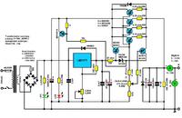
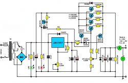
Below I am enclosing a diagram of the discussed power supply adapted to the mains transformer with 15VAC voltage on the secondary side, as my colleague has. There is a certain regularity in the construction of a linear power supply (after Low-Drop power supplies), where in a power supply with an output voltage of 14 ... 15VDC, a mains transformer with a secondary winding with a voltage of about 17 ... 18VAC should be used (the difference between the values of these voltages should be be at least 3V), especially when it is a high-current power supply. Returning to the power supply, for correct operation the LM317T stabilizer at the input should have a certain voltage reserve in relation to the output, and this voltage difference should look like this: Vin - Vout = approx. 3V. A 2.2k potentiometer and a 220 Ohm resistor set the maximum voltage at the stabilizer output to + 13.8V. Complex power transistors (BD911 + 4 x KD502) are connected to the output of the LM317T stabilizer, which work in the Darlington system, which causes the voltage at the output of the power supply to be reduced to about + 12.5V (this is the voltage + 13.8V minus the voltage 1.25V - threshold voltage of complex transistors in the Darlington circuit). It follows that at the LM317T input the appropriate voltage must be maintained for the entire power supply to work properly, i.e. to effectively stabilize the output voltage of + 12.5V, although I believe that for effective stabilization of this voltage the transformer could have a slightly higher voltage on the secondary side .
The discussed power supply has a current limiting range from 1 ... 1.5A to 8A ... 10A.
By increasing the values of the resistors (e.g. to 4 x 0.47 ... 0.56 Ohm / 5W) installed in the emitters of the power transistors (KD502), we reduce the minimum and maximum range of current limitation and vice versa by reducing the value of the resistors (e.g. 4 x 0, 33 ... 0.39 Ohm / 5W), we increase the minimum and maximum range of current limiting regulation. This reduction of the value of the emitter resistors must be handled carefully, because in the event of a short-circuit of the output sockets, the short-circuit current will exceed the maximum current limiting range and the power transistors may not "withstand" it ... (a fuse must be installed to prevent this from happening).
In the diagram, I marked the possible replacement of the 470 Ohm / A potentiometer (current regulation) with a 1k / A potentiometer, so that the current limiting adjustment at the maximum range was more convenient at lower voltages set at the output of the power supply. But you also have to be careful when replacing the potentiometer with 1k / A, for example, when the potentiometer slider is connected to a 4.7k resistor, because the short-circuit protection may not work and the power transistors will be damaged ... (to prevent this, a fuse must be installed) ).
When testing the current limitation, I advise you to use a suitable rectifier (four diodes + capacitor 30000uF / 35V) with a transformer of appropriate power (P = 150 ... 200W). This power supply must use four control transistors connected in parallel with the selected resistors in the emitters. I suggest you read post # 36 about a similar power supply carefully and my comment on its output voltage stabilization. The case of not the best voltage stabilization at the output of this power supply at the maximum load current (10A) also applies to the power supply discussed here. I also suggest carefully checking the elements for suitability, whether they are damaged, and the connections between them. The diagram clearly shows how the elements are to be connected in relation to the ground and how the ground is to be routed to the output socket.
Hello Krzysztof723 you say that to protect the transistors you need to give a fuse. Where exactly and how strong? Which of these transistors should be placed on the heatsink (I know for sure DB249C, and the others and the LM317 chip?) And what large heatsink should be for a single transistor or all of them? I have no experience with selecting heat sinks. For me personally, the range of the current limiter 0.1-5A for 0-25V voltages would suffice. In such a case, 4 BD249C transistors are necessary or, for example, 2pcs are enough? Is there any formula to calculate the needed emitter resistors depending on the current regulation we want to achieve? I would like to be able to go as low as possible to e.g. 100-200mA and to 5A at the top of the scale. Low limitation is important for circuit testing. Can you go so low? And the last question, does the capacitor behind the bridge have to be 30000uF or would a smaller one, e.g. 4700uF, be enough, if I would like to get max 5 A at the output of the power supply? Thank you very much for any helpful answers.
With the power supply current efficiency up to 5A - the fuse in the primary winding of the transformer is about 2 ... 2.5A, and in the secondary winding 6 ... 7A. The locations of the fuses are shown in the diagram. In this power supply, with the current efficiency of the power supply up to 5A and an adjustable output voltage of 0-25V, two BD249C transistors can be used (it is better to use two transistors in the TO-3 housing, such as e.g. KD502, MJ15003 etc.) placed on a finned heat sink with dimensions about 20cm x 10cm. Additionally, a fan can be blown on the heat sink from the side of the fins. The LM317T stabilizer and the BD911 (BD243) overload transistor can be screwed to e.g. 20mm x 20mm aluminum plates. If the power supply is assembled with LED overload signaling, the values of the emitter resistors will be 2 x 0.56 ... 0.62 Ohm / 5W, and when without signaling, the resistor values must be set at 2 x 0.47 Ohm / 5W. You cannot lower the minimum range of current limitation to 0.1A and in this case I suggest looking for a different power supply system. The filtering capacitor with the current efficiency of the power supply up to 5A can have a value of 10000uF / 50V (2 x 4700uF / 50V - connected in parallel).
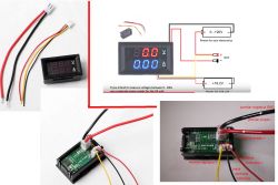
I assembled such a power supply according to the diagram from Krzysztof's last post # 101 and took off from the flight (printing of the boards on the knee with a pencil and on the boards with a marker, so I do not have a printout ...). The AC path is based on a transformer from a powerful Modecom UPS (around 450-500W, 2 secondary windings connected in series, after straightening and filtering, give about 19V under load - this is probably a standard in UPSs with a 12V battery), housing also from this UPS, bridge 50 A, single 10,000 miF filter conduit. The power supply after a slight modification of the voltage regulation (a 470Ohm resistor added in series to the 2.2 kOhm potentiometer) has a regulation from 2.8 to less than 15 V (I chose it for my needs) and the current is not too high - I forced 6 A from it at 10 V - surely related to emitter resistors. I couldn't get 0.39 Ohm anywhere, and only 0.31 and 0.47 Ohm were available immediately, so for fear of weakening the power transistors, I put 0.47. Probably from 0.39 the power supply would pull out the 10 A (if I get it, I will insert it). The power transistors are 4XTIP 35C on a large heat sink and a separate board with resistors (a little space in the middle of the housing). I added a double digital V and A panel meter with an overload indicator diode inserted in the middle and the additional third terminal led out the voltage immediately after the rectifier (i.e. less than 20V at a current> 20A) through a thermocouple for Heavy Duty applications (motors, large receivers - almost a welder came out) ). And that was it - a simple circuit power supply with regulated current and voltage that works AFTER NOW. Thank the author for the construction.
Hello gentlemen, I know that the topic is old, but I made this power supply from P. Krzysztof's scheme, but instead of the 47 resistor? 2W I gave 47? 3W. and also i have no current regulation. Could this resistor be the cause?
Ok, thank you for the quick answer, the circuit works, I didn't look at the PCB on which I had an error, because the base of one of the BD911 transistors was "hanging". I only have one more question, can I replace the MBR360 (SK304, SB360) diode with another, more accessible one? If so, which one? And I can give this BD140 transistor, for example, BC557 instead?
mario8423 You can replace the BD140 with the BC557 transistor. Powering the LED diode does not require that much current. However, the MBR360 Schottky diode (3A 60V) in this system is not necessary, it can be replaced with another one with similar parameters. greetings
Below I am enclosing a diagram of the discussed power supply adapted to the mains transformer with 15VAC voltage on the secondary side, as my colleague has.
Mr. Krzysztof,
How would this diagram and the parameters of the entire system change if a FEAS model power supply was used instead of a mains transformer? PSU500L24 with the following parameters:
How would this diagram and the parameters of the entire system change if, instead of a mains transformer, a FEAS PSU500L24 power supply with the following parameters was used:
As it can be seen from the description, this power supply has a mains transformer, a rectifier bridge and filtering capacitors, i.e. the 24VDC voltage at the output of the power supply is smoothed but not stabilized. I do not see any problems with connecting this Uwy - 24VDC power supply instead of a mains transformer, although taking into account the components used in it, the power supply with the LM317T would need to be removed from the rectifier bridge (diodes) and the 30000uF capacitor (the 10A fuse remains). Parameters, diagram - component values and configuration of the power supply connections on the LM317T will not change. You can extend the output voltage range to + 15V with a 220 Ohm resistor by changing its value to 180 Ohm.
Hello! A question to Mr. Krzysztof and / or other forum users: is it possible to easily adapt mosfet transistors to the power supply of P. current. Of course, after using or building the correct transformer.
Knock Knock! Anyone else coming here? Buddy krzysztof723 activate, please! I am in possession of two 2x7.5V + 28V (28V low current) transformers, they come from the UPS. Externally they look the same, but one weighs 2.28 kg, the other is 10 dkg heavier. I would like to take full advantage of the properties of these transformers by building some universal power supply, in which I would install a USB socket to charge the phone or tablet (independently). I would see acid batteries charging (and others?) Here. Maybe protection in the event of a short circuit by mechanical disconnection of the output terminal and LED + buzzer? Maybe a friend has something like that in his head? greetings
Hello! Silence in the topic, so I decided to implement one of the power supplies from the crowd of topics on the forum as part of the loose winter runs. The assumptions are: everything from recycling except electronic actuators or those that I do not have. Aesthetics is a quaternary thing and, therefore, hand-made elements, if necessary, such as the manufacture of a transformer. The cost in live cash is up to PLN 200. I converted the transformer from a microwave, because dogs hang terribly on the forum on these hits, that they are welded, that losses are not suitable, etc. In fact, to get the parameters as such, you need to double the primary and here I got from almost 3A to idle 0.36A, but unfortunately I had to compromise, because I would not press the secondary one with a decent diameter of wire according to the conversion factor of 3A per mm sq. This is to be bypassed, but I didn't get another identical hit. The transformer, in short, has three separate coils on the secondary, but they are bifilar wound (in fact, the wire is recycled and there are as many as 12 of them, but they are divided into two windings in each coil). The control takes place via 9 automotive relays controlled by a 12-position single-line switch via 12 transistors and powered by a separate small transformer. In this way, I obtained 12 thresholds, roughly a step of 2V to 3V depending on which coils are connected. There are fractions, but the machine works and I don't remember what the exact voltages were before the bridge and filter. In total, the step control behind the bridge came from 2V to 35V with a bit. Due to the fact that the total cross-section of the secondary windings does not meet the above-mentioned condition, the way of connecting individual coils is such that up to 6 positions, i.e. almost 14V, you can easily take 20A, above max 11A. I will, because I have provided this option, also an automatic winding switch, but now I do not have time, so next winter the work is as it was. There is also microwave cooling. Heatsink of the dispute also made of 3mm aluminum sheet. Housing from some sort of ventilation tunnel from an old hood. The base is made of an old wall unit. We bought transistors, emitter resistors, zener diodes, and capacitors because the recycled ones were scrap.
Now the most important thing, because everyone who reads this is shouting at me, I chose the project of Mr. Krzysztof723 from the topic: Power supply 1.25 to 25-30V10A with short-circuit protection, post No. 18 fig 6. The changes I made were 0.33 ohm emitter resistors for bd249c transistors, I added a fourth bd250c transistor, a diode on the schottky 20A-200V output because that was what I had and small diodes that I had at hand, so that they only meet the conditions of the diagram. The power supply is huge, because I did not play with miniaturization, besides, the fingers are not the same, and I packed it quite densely. The voltage jump at the output does not exceed 4V. I even reworked the microwave soft starter because the original one turned out to be too weak, but not because of the load, only the additional elements of the microwave, which are not here, are involved in its work. In my opinion, it is unnecessary for me because I have a strong 16A installation and 2.5mm square wires for sockets. The power supply took off and the only change I made after starting it was to change the resistor at the LM350 from 210om to 110om because it limited the voltage to 25V, and now I have to 32V. I couldn't test its boundary parameters for a long time, anyway I had no such need, because everything I needed was fed to me without any problems. Today I came into the possession of a resistance wire, from which I made something like a resistor and I did a few tests, for example: from idle voltage of about 22V it stabilizes my voltage of 12V to max 16A, from idle voltage of 32V it stabilizes my voltage of 24V up to max 7.5A. The current limitation, of course, depends on the set voltage and load, but when the bulb is loaded with about 8A, lowering the overload signaling turns on at 5A, but here the idle voltage was set with taps to 18V or 20V and adjusted to 12V. Depending on the set voltage with taps, it starts to lower the voltage at various points, but one thing is noticeable that when the overload is signaled, the voltage drops sharply. Nevertheless, the current can be further limited to about 2A, but the meter is analog, there is probably some error. The overload signaling is interesting, i.e. it goes out only above 4V at idle, but lowering the voltage, it lights up only at 2V, of course at idle. It doesn't bother me, and I haven't thought about it too much. Probably the transistor closes and opens in this spread and one of the resistors would have to be changed, or it is related to the charging of filter capacitors. I did not check the maximum upper limit because the 16A was blowing on the switch setting above 6 positions, so I should not exceed these 11A at least until the transformer temperature monitoring and possibly other points were installed. From what I noticed, the bd250c emitter resistors were barely noticeably warm, and the 249c transistors and their resistors were grave cold. Short circuit test approx. 1 minute approx. 4-5A, no negative consequences. Let me put it this way: there is no madness, but this implementation clearly confirms that Mr. Krzysztof's project is not only correct, but allows a lot, including the use of elements from scrap, and is even perfect for a project commonly known as DIY. It allows you to connect, of course, to the right places, with all attachments, e.g. for automatic battery charging, etc. For the implementation of the so-called DIY for non-professional applications, and even to some extent such, the criticism about microwave transformers is completely unbelievable. These are normal transformers for specialized use and therefore their conversion is problematic due to welding and too small windows. It is enough to have a clean, same core and the problem is gone. I converted a smaller one into a welder for someone and they just keep talking. I myself have a welder of two of these and it works quite correctly and the time can be set from approx. 03 sec. up to 14 sec. Were it not for too large a difference between the hits (over 10%, approx. 14%), the action would probably be completely repeatable. The idea of building a structure with my own hands is sensible for me when it meets the above-mentioned minimum assumptions (the PLN 200 limit is a matter of assuming savings on the project). Building something only from ready-made purchased elements, in my opinion, does not meet the requirements of the DIY project. Over the years, this is the 5th or 6th power supply I have built, rather the first one that can be called fully regulated. I distributed the old ones and it was necessary to build a new one. I would like to add that the design is so simple that I put everything on a spider and even that was more comfortable for me due to the unusual dimensions of the power supply, i.e. long and narrow. I am satisfied and formally thank Mr. Krzysztof for a successful project.
The whole problem with the range of current limiting is to select the appropriate values for the resistors installed in the emitters of the power transistors, but more on that later.
Below I am enclosing a diagram of the discussed power supply adapted to the mains transformer with 15VAC voltage on the secondary side, as my colleague has. There is a certain regularity in the construction of a linear power supply (after Low-Drop power supplies), where in a power supply with an output voltage of 14 ... 15VDC, a mains transformer with a secondary winding with a voltage of about 17 ... 18VAC should be used (the difference between the values of these voltages should be be at least 3V), especially when it is a high-current power supply. Returning to the power supply, for correct operation the LM317T stabilizer at the input should have a certain voltage reserve in relation to the output, and this voltage difference should look like this: Vin - Vout = approx. 3V. A 2.2k potentiometer and a 220 Ohm resistor set the maximum voltage at the stabilizer output to + 13.8V. Complex power transistors (BD911 + 4 x KD502) are connected to the output of the LM317T stabilizer, which work in the Darlington system, which causes the voltage at the output of the power supply to be reduced to about + 12.5V (this is the voltage + 13.8V minus the voltage 1.25V - threshold voltage of complex transistors in the Darlington circuit). It follows that at the LM317T input the appropriate voltage must be maintained for the entire power supply to work properly, i.e. to effectively stabilize the output voltage of + 12.5V, although I believe that for effective stabilization of this voltage the transformer could have a slightly higher voltage on the secondary side .
The discussed power supply has a current limiting range from 1 ... 1.5A to 8A ... 10A.
By increasing the values of the resistors (e.g. to 4 x 0.47 ... 0.56 Ohm / 5W) installed in the emitters of the power transistors (KD502), we reduce the minimum and maximum range of current limitation and vice versa by reducing the value of the resistors (e.g. 4 x 0, 33 ... 0.39 Ohm / 5W), we increase the minimum and maximum range of current limiting regulation. This reduction of the value of the emitter resistors must be handled carefully, because in the event of a short-circuit of the output sockets, the short-circuit current will exceed the maximum current limiting range and the power transistors may not "withstand" it ... (a fuse must be installed to prevent this from happening).
In the diagram, I marked the possible replacement of the 470 Ohm / A potentiometer (current regulation) with a 1k / A potentiometer, so that the current limiting adjustment at the maximum range was more convenient at lower voltages set at the output of the power supply. But you also have to be careful when replacing the potentiometer with 1k / A, for example, when the potentiometer slider is connected to a 4.7k resistor, because the short-circuit protection may not work and the power transistors will be damaged ... (to prevent this, a fuse must be installed) ).
When testing the current limitation, I advise you to use a suitable rectifier (four diodes + capacitor 30000uF / 35V) with a transformer of appropriate power (P = 150 ... 200W). This power supply must use four control transistors connected in parallel with the selected resistors in the emitters. I suggest you read post # 36 about a similar power supply carefully and my comment on its output voltage stabilization. The case is not the bestvoltage stabilization at the output of this power supply at the maximum load current (10A) also applies to the power supply discussed here. I also suggest carefully checking the elements for suitability, whether they are damaged, and the connections between them. The diagram clearly shows how the elements are to be connected in relation to the ground and how the ground is to be routed to the output socket.
greetings
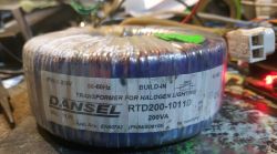
Mr. Krzysztof. In the New Year 2019, I wish you all the best and wish you all the forum members. I read this substantive thread carefully and I have a question. I have a 12V / 250VA troid transformer. 1. Can I use it for this project and what will the output parameters be? 2. If so, what modifications would I have to make? I would like to add that it usually does not operate with voltages greater than 18V and 5A currents - usually 6, 9 or 12V. Builds guitar effects and sometimes digital controls for them. Thank you in advance for your answer.
Hello Forgive me for answering so late, but better late than never. Probably, my friend, you have already dealt with another power supply project and that would be understandable. However, I will try to answer your questions, because it may be useful to others who would also like to assemble this power supply with a similar transformer.
You have a 12V / 250VA toroidal transformer, i.e. the secondary winding can be loaded with a current of about 20.8A. In order for this power supply to fully show its efficiency and effectiveness, a transformer with a secondary winding with a voltage of 27..28VAC / 12 ... 15A must be installed. . From this it follows that the voltage of 12VAC on the secondary of your transformer is not enough for this power supply, why I will explain this below.
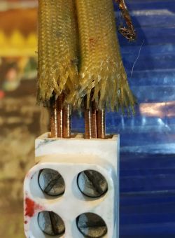
Sometimes the secondary winding in more powerful toroidal transformers is wound simultaneously with two identical conductors. If the secondary winding in your transformer is similarly wound, then after disconnecting the ends of the windings and connecting them appropriately (see the attached drawing), it can be used in the power supply discussed here.
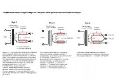
After connecting the windings as shown in the figure, your transformer will have a voltage on the secondary of 24VAC with a current load of up to 10A. And with a transformer converted in this way, you can build this power supply with an output voltage adjustable from 0 to + 20V.
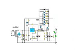
Looking at the diagram, it is not difficult to notice that the secondary winding does not have the so-called tapping. Such a tap on the secondary winding with a lower voltage would certainly help to reduce the loss power of the control transistors when lower voltages are set at the output of the power supply.
But...
It turned out that in this power supply, at low input voltages, e.g. + 21V (this voltage is obtained from the rectifier, when the transformer's secondary winding is e.g. 15VAC / 10A), the current efficiency at the output of the power supply drops to 4-6A in the regulated voltage range 0 ... + 12V (15V).
And just such a low current efficiency of the power supply (6A) was indicated by colleagues in previous posts, when they used transformers with a secondary winding with a voltage of 15VAC / 10 ... 20A or attached a direct voltage + 20V to the input of the power supply. And yet the power supply should work efficiently with a load current of up to 10A ... On the other hand, when the voltage at the input of the power supply was greater than +38 ... 39.5V (this voltage is obtained from the rectifier, when the secondary winding of the transformer is 27 ... 28VAC / 10A), the current efficiency of the output regulated voltage is 0... + 25V was kept almost in the whole range at the level of 8-10A.
Due to the lack of this tap, I used 6 control transistors to maintain the maximum current efficiency of the power supply with large power losses. With such a number of control transistors, the large power losses will be divided into individual transistors, ensuring their safe operation when the power supply output is loaded with the maximum current at low voltages set at the output of the power supply. For the safe operation of the transistors, a heat sink with appropriate dimensions should be used, along with additional cooling through forced air circulation by means of a fan (s).
If, however, it is not possible to increase the voltage on the secondary winding in your transformer (250VA - 12VAC) due to the fact that this winding is made with one wire, I suggest connecting an additional winding to the factory secondary winding in the amount of about 42 coils. Wind the wire in the same direction as the factory winding and the same diameter as the factory winding, then connect the start of the additional winding to the end of the factory winding and we get a voltage of about 24VAC / 10.4A. By increasing the number of turns to about 52, we get a voltage of about 27VAC / 9.2A on the secondary winding.
If the transformer conversion could not be performed, it remains to use a voltage doubling rectifier. It's not a perfect way, but it does the job. Once, for the test, I assembled a rectifier in such a connection system with a 150VA - 12VAC / 12.5A transformer and with a load of 5A at the rectifier output I got + 19V ...
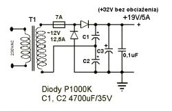
You wrote my friend like this: "I'll add that it doesn't usually operate with voltages greater than 18V and 5A currents - usually 6, 9 or 12V. It builds guitar effects and sometimes digital controls for them."
Therefore, using a voltage doubler rectifier you will be able to build a power supply as below with an output voltage of 0 ... + 15V with a current efficiency of up to 5A.
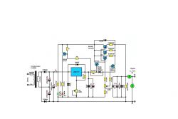
Mr. Krzysztof, The answer is by no means late. I am in travels and have much less time for my projects.
I read your answer carefully. After reading it carefully, I took a closer look at my transformer. And it is labeled as 200VA and 11.5V. But it has a triple winding, I believe (as can be seen in the lead). Can I then try to connect these windings in series to reach 34.5V on the secondary side?
PS. I realize that my question does not apply exactly to this thread. If so, please let the moderator inform you about it.
To the author (Mr. Krzysztof). I finally put in emitter .31 ohm resistors (previously I had 0.47 just in case with the total current below 10A - I'm reckless and my madness usually ended with smoke from some constructed system and now the risks - a physicist, as I wrote earlier - I have quite efficient transistors ) and the power supply acquired a concrete almost 20 amps (exactly cut-off at 17.3A) without anything warming up. Enough electricity for me. The cut-off and current control as well as the voltage regulation work fine, although the current and voltage adjustments are slightly non-linear. As I wrote earlier - I added a current monitor on the shunt and a voltmeter made in PRC and everything works like a watch.
I am asking for more such simple and functional ideas.
PS. I am not an advanced electronics engineer and tried tons of power supply ideas. This one is the first (and I suspect the last - because it works perfectly) that he broke from the start. IT WORKS.
@kotbury Thank you for these positive comments, it's nice to work with someone who sees and understands my projects so well, without belittling others of course.
Added after 4 [hours] 23 [minutes]:
mastad wrote:
... I took a closer look at my transformer. And it is labeled as 200VA and 11.5V. But it has a triple winding, I believe (as can be seen in the lead). Can I then try to connect these windings in series to reach 34.5V on the secondary side?
The 200VA / 11.5V transformer has a current efficiency of up to 17.4A. The secondary winding is wound with three wires at the same time (so you say, buddy), and then each wire of the appropriate diameter is adapted to a load with a current of 5.8A. In the case of the discussed power supply, three windings cannot be connected in series, because after connecting and obtaining an alternating voltage of 34.5VAC, and then after rectification, we will obtain 48.6VDC with a current efficiency of 5.8A on the filtering capacitor. The maximum voltage that can be supplied to the input of the LM317T stabilizer is + 40V.
But ..., the photo of the entire transformer is hardly visible (especially the external - secondary winding) and here you need to pay attention whether this winding is actually wound with three wires, because the terminals shown in the photo may not necessarily indicate a winding consisting of three wires .
If, however, it was a winding consisting of three wires, it would belong to the construction of a power supply with an output voltage. 0 ... + 20V / 5A use two wires connected in series 23VAC (after rectification + 32.4V), and the third winding 11.5VAC (after rectification + 16.2V) to power the module with a voltmeter - ammeter.
It is also possible to use your transformer to build a power supply with an output voltage of 0 ... + 30V / 5A, but you will need a stabilizer LM317HVT.