logo elektroda
logo elektroda
X
logo elektroda

Regulated power supply (darlington power) for LM317 10A 1.2..37V

kozak84 233528 121
ADVERTISEMENT
Treść została przetłumaczona polish » english Zobacz oryginalną wersję tematu
  • #61 14439723
    laciaty1981
    Level 12  
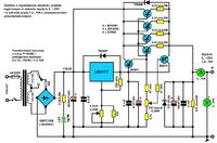
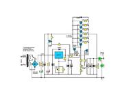
    This is the circuit diagram, but I changed the extension to "mp3" it should be "brd" because it was not included. But this circuit is not working properly. When I changed the emitter resistors to the value of 8.2 ohms, there was just some current regulation but everything was warm and I do not know what to do with this system. Can anyone help???
  • ADVERTISEMENT
  • #62 14451461
    moun
    Level 1  
    I know you will find my question strange, but in different places I saw different marking of the LM317 terminals, what is real or 1-IN; 2-Reg; 3-OUT (according to the scheme) or 1-Reg; 2-OUT; 3-IN. Thanks for the help.
  • #64 14527740
    mayzel
    Level 14  
    krzysztof723 wrote:
    Regulated power supply (darlington power) for LM317 10A 1.2..37V

    Added after 9 [minutes]:

    Hello

    The attached drawing shows a simple power supply with adjustable output voltage in the range of 0V ... 25V with adjustable output current limitation in the range of 1.5 ... 10A and with foldback protection.
    .


    Hi everyone ,

    A question for Krzysztof, ... ;) well let's go further, ... ;) .. on the basis of your project, it would be possible to expand the power supply to 30 A and voltage 13.8V? ... Bigger 600VA transformer? Bigger 50A bridge?
    I think, is it just the KF 100W transcirver that would not fit such a design ..
    Thank you in advance for the information.

    greetings
  • #65 14531700
    krzysztof723
    Level 30  
    laciaty1981 wrote:
    Hello, I will warm up the topic because I have a problem with the power supply (Mr. Krzysztof723) from the post No. 53, it is about PCB No. 2, I made such a PCB and assembled the system and it turned out that the current regulation with a 500ohm potentiometer does not work after the system is loaded with a receiver. Voltage regulation works fine. When increasing the voltage, the current increases, but I cannot lower it or increase it with a 500ohm potentiometer. The system is powered by a 24v 630VA transformer, 50A bridge, 18800uF 63V capacitors.
    I am asking for a hint what I did wrong.
    Greetings. Regulated power supply (darlington power) for LM317 10A 1.2..37V


    laciaty1981 wrote:
    I have already figured out why I did not have current regulation - you need to choose emitter resistors.


    laciaty1981 wrote:
    But this circuit is not working properly. When I changed the emitter resistors to the value of 8.2 ohms, there was just some current regulation but everything was warm and I do not know what to do with this system. Can anyone help???


    Did you deal with the problem of current limiting regulation?
    Not every day I check the Electrode and the mailbox and that's why I missed your entries, and after that I am a bit busy with other things recently.
    Replacing the emitter resistors with 8.2 Ohm is an exaggeration. It is enough to select emitter resistors in the range of 0.39 ... 0.68 Ohm / 5W with four transistors - if the current limiting regulation is to be up to 10A.
    Check if the BD911 transistor (the base connected to the 470 Ohm potentiometer through the 47 Ohm resistor) is not damaged. This transistor should be placed on a small heat sink (e.g. 50mm x 50mm x 2mm aluminum plate).
    Check carefully the values of the elements responsible for the current limiting adjustment range: 4 x 0.39 ... 68 Ohm / 5W, 2 x 47 Ohm / 0.25W, 4.7k / 0.25W, linear potentiometer 470 Ohm / 0.25W - Also check the potentiometer mechanically.
    Well-designed board, error in the schematic (but not on the board) - transistor collectors are not connected to the "+" input.
    If there are still problems with adjusting the current limitation, we will try to fix it step by step.
  • #66 14540279
    krzysztof723
    Level 30  
    mayzel wrote:
    A question for Krzysztof, ... :wink: well let's go further, ... :wink: .. on the basis of your project, it would be possible to expand the power supply to 30 A and voltage 13.8V? ... Bigger 600VA transformer? Bigger 50A bridge?
    I think, is it just the KF 100W transcirver that would not fit such a design ..
    Thank you in advance for the information.


    I designed and checked the power supply included by you with a load current of up to 10A.
    Expanding this power supply (adding regulating transistors) to a current capacity of 30A will not be a good idea.
    This power supply does not have the best voltage stabilization at the output at a load of e.g. 10A, and increasing the load to 30A will significantly worsen this stabilization.
    A good high-current power supply for your transceiver would be a power supply built on the popular circuit - pnp power transistors + LM stabilizer ...
  • #67 14547994
    mayzel
    Level 14  
    Thanks Krzysiek for the answer. I will deal with the power supply for the KF transcirver later ;) , we come back to the topic of your power supply. I have a transformer of 250VA and one secondary voltage of 33V, or is it sometimes too "rich" secondary voltage? .. The capacitor bank will increase to over 36V, the LM317 will be on the edge of the range. Although I have a 50mmx30mm ribbed heat sink, it may not last long :D

    greetings


    Irek
  • ADVERTISEMENT
  • #68 14552032
    krzysztof723
    Level 30  
    mayzel wrote:
    ... back to the topic of your power supply. I have a transformer of 250VA and one secondary voltage of 33V, or is it sometimes too "rich" secondary voltage? .. The capacitor bank will increase to over 36V, the LM317 will be on the edge of the range. Although I have a 50mmx30mm ribbed heat sink, it may not last long :D


    The 33VAC secondary transformer is unsuitable for the power supply we are discussing here.
    With this AC voltage after rectification on the capacitors will be 46VDC. Too much for the LM317T.
    The LM317T stabilizer can work with a maximum input voltage of 40VDC and therefore a pair of coils should be unwound to obtain the maximum voltage of ~ 26V at a fixed voltage at the output of the power supply 0 ... + 25V.
    If the secondary winding does not have a tap, then attention must be paid to the loss power of the power transistors (sufficiently large heat sink, additional fan cooling), when the voltage at the output of the power supply is low and the load current is high.
    In addition, the winding wire in the secondary winding of your transformer is adapted to a load with a current of up to 7.5A (more specifically the wire diameter), therefore the parameters of the power supply's current efficiency must be changed by appropriate selection of the emitter resistors.
    To a separate, similar heat sink that you used for the LM317T, you should screw the BD911 transistor, the base of which is connected to the slider of the 470 Ohm potentiometer.
  • #69 14553454
    mayzel
    Level 14  
    Thank you for your response,
    A typo crept into my enumeration; ), of course, I meant the voltage value of 46V, thus I would not develop the topic of LM317 strength :D because it is obvious in this case.

    Anyway, I already know that I have to look for a transformer with max voltage on the secondary to about 25 V.
    ---------------------------
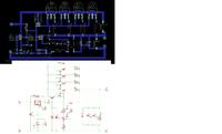
    These are planned PCBs for the power supply, I have a question; Will the method of mass handling in this case be appropriate? Regulated power supply (darlington power) for LM317 10A 1.2..37V

    Any criticism appreciated :D

    greetings
  • #70 14554493
    krzysztof723
    Level 30  
    mayzel wrote:
    about the planned PCBs for the power supply, I have a question; Will the method of mass handling in this case be appropriate?

    Any criticism appreciated


    The correct way of leading the mass is presented on the plate from post # 53 and on the plate made by a colleague of years 1981 from post # 63.
    Bearing in mind your board, I suggest you make changes as shown in the drawing below.
    The bridge rectifier should be of the KBPC1506 type with a small heat sink, and not of the KBL ... or KBU ... type.
    You need to add a 0.1uF capacitor near the LM317T's middle foot.
    You have not solved the position of individual elements in the best way (e.g. the voltage adjustment potentiometer is too far from the LM317T), but the board has already been designed and after the correction I suggest, the power supply should work without any problems.

    Regulated power supply (darlington power) for LM317 10A 1.2..37V
  • #71 14581024
    laciaty1981
    Level 12  
    Hello, after a long break.
    I have not dealt with the current limitation yet and I have not fully done everything that Mr. Krzysztof suggested. I checked the transistor, potentiometer and resistors from the potentiometer to the reg. current and parameters are fine.
    I had to change to even larger emitter resistors because I tried with 0.33ohm and 0.47ohm. (a small selection in the store, I will buy other resistance on the Allegro)
    To load the system, I used two h4 bulbs connected in parallel and set the voltage to 12V, the current consumption is about 8A.
    Thank you for your interest, Mr. Krzysztof.
    Greetings.
  • #72 14581297
    krzysztof723
    Level 30  
    So I understand that with 0.47 Ohm / 5W resistors you have already tried to adjust the current limit and there is still no regulation, right?
  • #73 14582349
    laciaty1981
    Level 12  
    Yes I tried 0.47ohm and no effect. Maybe it's important - I used only three resistors (I disconnected the fourth one because they only had that much in the store and 0.33ohm I had four)
    I also made a test with three 0.6A resistors and the current adjustment is 0.3A.
  • #74 14588051
    krzysztof723
    Level 30  
    laciaty1981 wrote:
    Yes I tried 0.47ohm and no effect. Maybe it's important - I used only three resistors (I disconnected the fourth one because they only had that much in the store and 0.33ohm I had four)

    Let's put it all in order.

    Assemble the power supply correctly according to the diagram - use four transistors and four emitter resistors and write down how the current limiting regulation works.
    By the way, check the spacing between the tracks, where the transistors are soldered, if there are sometimes any traces of copper particles that could connect the tracks.

    laciaty1981 wrote:
    I also made a test with three 0.6A resistors and the current adjustment is 0.3A.


    Expand that thought of yours. What does 0.3A mean?
  • #75 14588140
    laciaty1981
    Level 12  
    These 0.3A, that is: the bulbs consume 8A at about 12V. By turning the 470ohm potentiometer to its extreme positions, the difference is 0.3A, i.e. from 7.7A - 8A.

    When I get these resistors, I will check it carefully.
    (the plate etched nicely, but I redraw the spacing between the legs)
  • ADVERTISEMENT
  • #76 14588157
    mayzel
    Level 14  
    Hi everyone,

    Krzysiek and laciaty1981, I can see that there is a discussion between you :D but let me go between the words.
    Krzysiek, the current measurement is carried out in the power supply with the participation of the tilt meter in the positive voltage branch. Does the ammeter in this case indicate the value of the current measurement, or the current limit indication?
    I have two gauges; AVT 2857 on LCD and from Darek Link ammeter on LEDs. I wanted to adapt them to the power supply. In AVT2857 and in this one from Darek, the current measurement is in the minus, in your diagram it is in the plus :) ... will anything come of this? :D
    Can two ammeters be used, one of which will show the current consumption measurement and the other will show the set value of the current limit?

    Irek
  • #77 14641544
    mayzel
    Level 14  
    Hey, something about sat down ;) . how is the work on the power supply?
    Łaciaty, did you do something? ... ;) I am in the process of completing components and PCBs. I will try to communicate the results soon ......... ;)

    greetings
    Irek
  • #78 14649583
    laciaty1981
    Level 12  
    Hello, I have already bought resistors but I have not yet had time to solder and check them. I will try this week.
  • #79 14680747
    mayzel
    Level 14  
    Hi,
    I have assembled the power supply, so far without the housing :) . I used a 250VA 2x17V transformer
    I thought that I would have no problems regulating the current? ... (current limitation? ..) However, like the others, I do not have current regulation at all. Elements according to the scheme. Since Łaciaty has already tested 0.33R resistors, I went with a "thick pipe" :D and mounted 0.1R emitters. However, no effect so far. I still have 0.15R 0.10R in stock, but something and it seems that replacing them will not change the state of affairs.
    I tested the power supply under a load from 0.5A to 2.5A. The temperature of the BD249 transistors is within 38 C. What's interesting, the current control potentiometer is also slightly warm. LM317 and BD 911 as cold as the Arctic :D . I would like to add that I read the current using a digital meter, where it is connected to the positive branch (ammeter).
    And what's next... ;) how to live ..., replace emitter resistors? .. change the meter to an ordinary analog pointer? .. What should the ammeter show when turning the potentiometer 470R; current protection threshold value? whether at the moment the value of the current consumption by the connected receiver.
    Krzysiek, do you have any tips? ideas?... :D

    .......
    I "discovered" something :D ... Because my power supply consists of separate modules, that is, separately; driver board and separate board with executive transistors which are connected with 1.5mm2 wires, I disconnected the executor module from BD249. There are two BD911 and LM317 on the driver's board and the whole stall :D with potentiometers for adjustment.
    I connected a receiver for testing purposes and it consumes only 200mA. And what is happening .. ;)
    Suddenly I can adjust the voltage range, albeit only from 1.20V to 17V, but simultaneously turning the potentiometer to the current, I have a range of 0-200mA. I do not want to connect a larger receiver without BD249, but you can see that the idea of regulation is kept, ..... but why does it not work in conjunction with BD249 transistors? ....... ;)
    .................
    I changed the emitter resistors to 0.15R, reconnected the executive module, loaded the receiver with a consumption of 0.5A and ...? ... :cry: no current regulation.
    End of ideas, .. I'm going for a beer
    :evil: :evil:
  • #80 14689872
    krzysztof723
    Level 30  
    mayzel wrote:
    I thought that I would have no problems regulating the current? ... (current limitation? ..) However, like the others, I do not have current regulation at all.


    In that case, please be patient, I have to rebuild this power supply and check why there are problems with adjusting the current limit.
    It may take from several to several days.
    Lack of time limits me to solve this problem faster.

    mayzel wrote:
    Elements according to the scheme. Since Łaciaty has already tested 0.33R resistors, I went with a "thick pipe" :D and mounted 0.1R emitters. However, no effect so far. I still have 0.15R 0.10R in stock, but something and it seems that replacing them will not change the state of affairs.


    Wrong you came from the "thick pipe" ...
    The value of emitter resistors should be increased e.g. to 4 x 0.68 Ohm / 5W, and not decreased to 4 x 0.1 ... 0.15 Ohm / 5W.
  • #81 14694202
    mayzel
    Level 14  
    Hi everyone ,
    krzysztof723 wrote:

    The value of emitter resistors should be increased e.g. to 4 x 0.68 Ohm / 5W, and not decreased to 4 x 0.1 ... 0.15 Ohm / 5W.


    Thanks Krzysztof for the response, well, I changed it to 0.68R, although it didn't work anyway. I still have 1R resistors in stock, but it probably won't change anything :D
    Nice power supply, voltage regulation works great, current is fine :D , it easily works with my VHF radio, where the transmission is up to 8A power consumption at 25W. ..Only this current limit adjustment ....... :crazyeyes:

    greetings
    Irek
  • #82 14743376
    krzysztof723
    Level 30  
    Hello

    To my friends laciaty1981 and mayzel
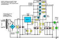
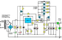
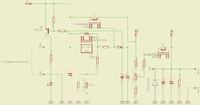
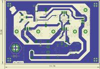
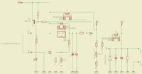
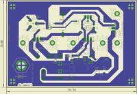
    You were right, gentlemen, in the power supply from post # 45, the current limiting regulation did not work.
    I do not know how it happened that I included this diagram on the Electrode with an error in the schematic (one resistor missing).
    At the beginning, after assembling the power supply, I could not find out what was going on, because I always check all my projects in practice and as I remember, I also checked this power supply.
    Well, everything turned out well and I am posting a revised schematic of this power supply.
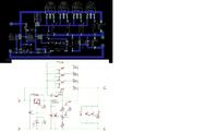
    In addition, I enclose a diagram of the power supply with overcurrent indication - LED.
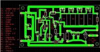
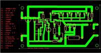
    I corrected my friend laciata1981's plate and two plates from post # 53.
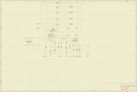
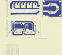
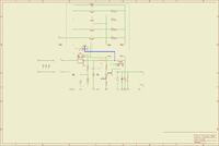
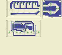
    Regulated power supply (darlington power) for LM317 10A 1.2..37V Regulated power supply (darlington power) for LM317 10A 1.2..37V Regulated power supply (darlington power) for LM317 10A 1.2..37V

    Regulated power supply (darlington power) for LM317 10A 1.2..37V Regulated power supply (darlington power) for LM317 10A 1.2..37V Regulated power supply (darlington power) for LM317 10A 1.2..37V
  • ADVERTISEMENT
  • #83 14745864
    mayzel
    Level 14  
    Hey everyone,

    Krzysiek, I hopefully implemented the revised power supply diagram, but life is brutal :D . I did not have a diode at hand that goes after the 47r resistor, so I used the new diagram No. 1. Unfortunately, there are no changes to the current regulation. I used 0.33R emitter resistors that I had from previous trials.
    As you already know from my previous posts, my version of the power supply consists of a separate module with executive transistors. This board is connected to the "driver" module by means of 2.5mm wires. If I disconnect the BD249 transistors, the current limit is adjustable at the 0 .. + 25V output of the power supply . After reconnecting the BD249 unit, the above-mentioned regulation is again missing. I've been wondering what's wrong, I've been checking connections, elements all afternoon, no complaints in that respect.

    Łaciaty, let me know if the power supply starts working for you after the changes. It works for Krzysztof, as well as you, it means that something is wrong in my version, although I assure you that I redrawn the diagram for Eagle, checking it several times :D

    Irek
  • #84 14748122
    krzysztof723
    Level 30  
    To mate mayzel
    I assembled this power supply on the so-called spider, but after your last post with comments that the power supply still does not work properly, I desoldered the system completely, checked the components and reassembled the power supply.
    I did not insert a 47 Ohm / 2W resistor and the power supply did not have a current limit adjustment, I soldered the resistor as in the corrected diagram and the power supply has a current limit adjustment.

    What you wrote "If I disconnect the BD249 transistors, I have a current limit adjustment at the output of the power supply 0 .. + 25V" is a bit strange ...

    Turn on your PCB and show where you have inserted the 47 Ohm resistor, because if it is the PCB from post # 69, it is difficult to insert this resistor there without changing the position of the tracks and elements. Show - draw with lines how you connect the two tiles.
    +
  • #85 14748287
    mayzel
    Level 14  
    I completely changed the design from the original from post # 69. I decided to use separate modules because of the greater possibility of arranging them in the housing.


    The picture shows the way I turned on the 47r resistor. These are exactly two 100r resistors, but the resultant resistance of both of them is 49r. In the picture, I just wanted to show how I did it. Instead of R5 and R6, the cables have potentiometers 470r / A and 4k7 / A. The R 11 resistor is 47r, although the picture is 47k (error in the description, but not in use :)
    For a moment it seems to me that everything is in line with the new assumption of the scheme. Unless?..... ;)

    ps. I had to add pictures as attachments, because I couldn't enter something via "Add picture" :)
  • #86 14749097
    krzysztof723
    Level 30  
    To mate mayzel

    Circuit diagram errors:
    - the base of the T6 transistor should be connected to the collector of the T5 transistor and the 47 Ohm / 2W resistor, not to the OUT LM317T output,
    - potentiometer slider 470 Ohm / A and resistor R10 - 47 Ohm / 0.25W cannot be connected to the ground of the system,
    compare your schematic with the corrected one.

    PCB errors:
    - potentiometer slider 470 Ohm / A and resistor R10 - 47 Ohm / 0.25W connected to the ground of the system,
    - incorrectly connected 47 Ohm / 2W resistor, change the connections (paths) between the transistor T6 and T5, and the LM317T,
    compare your plate with the revised plate.

    Regulated power supply (darlington power) for LM317 10A 1.2..37V
    Regulated power supply (darlington power) for LM317 10A 1.2..37V
  • #87 14749874
    mayzel
    Level 14  
    OKAY :D
    Krzysiek,
    I admit that I was supposed to connect the T5 and T6 transistors in this way. Even Eagle suggested so with "unrouted" connections. However, I did it my way, because I didn't want to "complicate" my life on an already existing PCB more than necessary :D Just such laziness.

    Krzysiek, please, take a look at the version presented below according to your new scheme. I only changed the driver and haven't done it yet. If there is room for improvement, there is still time.
    Thanks in advance for everything :) Regulated power supply (darlington power) for LM317 10A 1.2..37V

    Regulated power supply (darlington power) for LM317 10A 1.2..37V
  • #88 14750678
    krzysztof723
    Level 30  
    Capacitors C7 - 100nF and C4 - 47uF / 35V wrongly connected.
    Compare your schematic and PCB with schematic and PCB revised.

    Regulated power supply (darlington power) for LM317 10A 1.2..37V
    Regulated power supply (darlington power) for LM317 10A 1.2..37V
  • #89 14788228
    laciaty1981
    Level 12  
    Hello, after a long break. Finally, I found time to take care of the power supply and made corrections according to Mr. Krzysztof.

    The power supply works !!!

    Thank you, Mr. Krzysztof, for your interest and improving the layout.
    greetings
  • #90 15078377
    Robcio_K
    Level 11  
    Hello.

    I have a question for the gentlemen who assembled and launched Mr. Krzysztof's power supply. Which of the available schematics has all the corrections applied? How is this power supply for you? Has anyone been using the maximum current for a long time?

    A question to the author of the project, out of pure curiosity - why the discrepancy in the setting of the current adjustment potentiometer - to the end at the minimum voltage and half at the maximum voltage?
    Second question: I have a 400 Ohm potentiometer on hand, which I am going to use to regulate the current. How much will the regulation range suffer from the lack of these 70 ohms?

Topic summary

The discussion revolves around the design and implementation of a regulated power supply using the LM317 voltage regulator, capable of delivering up to 10A with an output voltage range of 1.2V to 37V. Participants address various technical challenges, including heat dissipation, current regulation, and circuit stability under load. Suggestions include using additional power transistors (e.g., BD911, 2N3055) for increased current capacity, the necessity of substantial heat sinks, and the importance of proper circuit design to ensure voltage stability. Concerns about short-circuit protection and efficiency losses at high currents are also raised, with recommendations for using multiple transistors in parallel and optimizing resistor values for current limiting. The conversation highlights the need for careful component selection and circuit layout to achieve reliable performance.
Summary generated by the language model.
ADVERTISEMENT