logo elektroda
logo elektroda
X
logo elektroda

Flashing BL602 SDV-002_V1.2 Water Gas Shutoff Valve via BouffaloLabDevCube

lamero345 507 10
ADVERTISEMENT
  • #1 21769124
    lamero345
    Level 2  
    Name: Water Gas Shutoff Automated Ball Valve

    Url: https://www.aliexpress.com/item/1005007161169914.html

    Module: BL602 Module SDV-002_V1.2
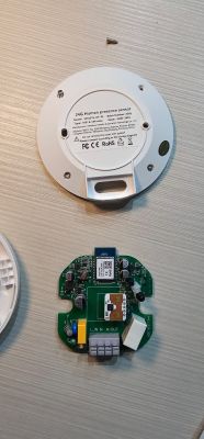
    Photos:

    Flashing BL602 SDV-002_V1.2 Water Gas Shutoff Valve via BouffaloLabDevCube

    Flashing BL602 SDV-002_V1.2 Water Gas Shutoff Valve via BouffaloLabDevCube

    Connection: Connecting a wire to R2 and connecting it to VCC during power on is enough to put the module in BOOT mode as described here. TX, RX, VCC and GND pins are as described

    SDV-002_V1.2 PCBs with pinout diagram and function descriptions in table.

    Logs: Before flash the module I get these values from UART log

    
    GPIO config is :
    cfg->wifi_led = 200
    cfg->led_status = 0
    cfg->led_ch_status = 1
    cfg->backlight_en = 0
    cfg->backlight_init = 0
    cfg->backlight_level = 0
    cfg->backlight_pin = 200
    cfg->led_level = 0
    cfg->led0 = 12
    cfg->led1 = 200
    cfg->led2 = 200
    cfg->led3 = 200
    cfg->relay_type = 0
    cfg->lr0_on = 200
    cfg->lr0_off = 200
    cfg->lr1_on = 200
    cfg->lr1_off = 200
    cfg->lr2_on = 200
    cfg->lr2_off = 200
    cfg->lr3_on = 200
    cfg->lr3_off = 200
    cfg->lr_pulse_width = 30
    cfg->lr_interval_width = 250
    cfg->all_on_off = 200
    cfg->relay0 = 2
    cfg->relay1 = 200
    cfg->relay2 = 200
    cfg->relay3 = 200
    cfg->key0 = 14
    cfg->key1 = 200
    cfg->key2 = 200
    cfg->key3 = 200


    Template:
    
    {
    "vendor": "TOMZN",
    "bDetailed": "1",
    "name": "WIFI Smart ATS",
    "model": "TOQ7E-125/4 220V",
    "chip": "BL602",
    "board": "SDV-002_V1.2",
    "keywords": [
    "switch",
    "relay",
    "button",
    "bl602"
    ],
    "pins": {
    "2": "Rel;1",
    "14": "Btn;1",
    "12": "LED;1"
    }
    }
    
  • ADVERTISEMENT
  • ADVERTISEMENT
  • #3 21769675
    insmod
    Level 29  
    >>21769124
    Do you remember what the problem was with BK7231GUIFlashTool?
  • ADVERTISEMENT
  • #4 21771871
    lamero345
    Level 2  
    Never starts backup or flash. I will retry with a new product on next week. I will try to do a backup also.
  • #5 21772611
    divadiow
    Level 37  
    ideal conditions testing with an ai-wb2-32s but I can flash OK at 921600 and it boots.

    Screenshot of BK7231 Easy UART Flasher with message “Writing done”
  • ADVERTISEMENT
  • #7 21776266
    divadiow
    Level 37  
    cool. here is full boot log

    Code: Text
    Log in, to see the code
  • #8 21787177
    p.kaczmarek2
    Moderator Smart Home
    I am reading this topic and I wonder. Aren't those pin indexes stored in flash somewhere? It looks like they are from C struct. I tried to search binary for 0xC8 (200) pattern, but didn't find good matches yet.
    lamero345 wrote:

    Logs: Before flash the module I get these values from UART log

    
    GPIO config is :
    cfg->wifi_led = 200
    cfg->led_status = 0
    cfg->led_ch_status = 1
    cfg->backlight_en    = 0
    cfg->backlight_init  = 0
    cfg->backlight_level = 0
    cfg->backlight_pin   = 200
    cfg->led_level = 0
    cfg->led0 = 12
    cfg->led1 = 200
    cfg->led2 = 200
    cfg->led3 = 200
    cfg->relay_type  = 0
    cfg->lr0_on  = 200
    cfg->lr0_off = 200
    cfg->lr1_on  = 200
    cfg->lr1_off = 200
    cfg->lr2_on  = 200
    cfg->lr2_off = 200
    cfg->lr3_on  = 200
    cfg->lr3_off = 200
    cfg->lr_pulse_width = 30
    cfg->lr_interval_width = 250
    cfg->all_on_off = 200
    cfg->relay0 = 2
    cfg->relay1 = 200
    cfg->relay2 = 200
    cfg->relay3 = 200
    cfg->key0 = 14
    cfg->key1 = 200
    cfg->key2 = 200
    cfg->key3 = 200
    

    Helpful post? Buy me a coffee.
  • #9 21787528
    divadiow
    Level 37  
    GPT is going on about it being stored as a flattened device tree (DTB).

    Screenshot of CMD terminal showing GPIO analysis from a Python script.

    This script seems OK at getting GPIOs for some dumps, though CozyLife seems different

    Code: Text
    Log in, to see the code


    Code: Python
    Log in, to see the code


    This could totally be a new BL602 config extractor tab in EF or something. A text window with json IO config translation for pasting into the web app import

    Added after 7 [minutes]:

    oh lol

    Code: Text
    Log in, to see the code


    Code: Text
    Log in, to see the code


    Added after 4 [hours] 37 [minutes]:

    fiddling
    Application window showing extracted GPIO results from BL602 .bin file
  • #10 21788392
    p.kaczmarek2
    Moderator Smart Home
    I am confused - is it reliable? Or is it giving false, non-existent pins?
    How did LLM know to use Flattened Devicetree (DTB) Format?
    Helpful post? Buy me a coffee.
  • #11 21788797
    divadiow
    Level 37  
    OK, so it's just early trying things.

    I've taken a step back to work on a more basic script.

    Code: Python
    Log in, to see the code


    Code: Text
    Log in, to see the code


    Code: Text
    Log in, to see the code


    That dump is from this device with this template

    Code: Text
    Log in, to see the code


    so we see the 3 pins are clearly retrievable from the dump.

    Another one:

    Code: Text
    Log in, to see the code


    Code: Text
    Log in, to see the code


    which kinda matches this https://www.elektroda.com/rtvforum/topic4009765.html#20795350

    Code: Text
    Log in, to see the code


    Added after 25 [minutes]:

    hmm. this next script should print more (attached as zip)

    Code: Text
    Log in, to see the code


    Code: Text
    Log in, to see the code


    OBK config for this bulb is

    "3": "PWM;5",
    "14": "PWM;1",
    "20": "PWM;2",
    "21": "PWM;3",
    "22": "PWM;4"

    not sure how to translate what's printed out into a working template in this case

Topic summary

The discussion focuses on the TOMZN WIFI Smart ATS device featuring the BL602 Module SDV-002_V1.2. The user attempts to flash the module using BK7231GUIFlashTool v154 without success, but succeeds with BouffaloLabDevCube v1.9.0, applying specific firmware components including partition_cfg_2M.toml, OpenBL602_1.18.214.bin, bl_factory_params_IoTKitA_40M.dts, and boot2_isp_release.bin. The module enters BOOT mode by connecting a wire from R2 to VCC during power-on, with TX, RX, VCC, and GND pins correctly identified. UART logs reveal GPIO configurations related to wifi_led and led_status. A linked GitHub pull request (OpenBekenIOT/webapp#237) and images provide additional technical context. The main issue involves the smart switch flipping from position A to B upon reboot, indicating firmware or hardware behavior under investigation.
Summary generated by the language model.
ADVERTISEMENT