In the topic about the component tester
LCR M328 Information about the possibility of changing the microcontroller firmware has appeared. I decided to check it in practice, despite the risk of breaking the device. Since the last tests, I have secured the LCD against falling out with a thermal glue and secured with a piece of stiff foil a flexible tape connecting the LCD with the board.
The software and documentation of the microprocessor tester can be found here:
https://www.mikrocontroller.net/svnbrowser/transistortester/ I suspect that all available LCR testers have software based on these sources.
We click
"Download GNU tarball" and extract the content (e.g. using 7zip).
We will use the source code to work with
Atmel Studio 7. After installing the Atmel Studio 7 environment, select:
File -> New -> GCC C Executable Project, select the ATMEGA328P microcontroller and create a project with the selected name in the selected location.
We copy all files from the directory with unpacked contents \ Software \ trunk \
to the directory of the created Atmel Studio project (where the .cproj file is),
then we agree to replace main.c.
Copy the "fonts" and "mega328_st7565" directories from the \ Software \ trunk \ directory to the project directory.
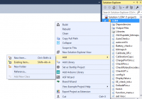
Right-click on the project name in the solution explorer window and select:
Add-> Existing items let's add all * .ci * .h files
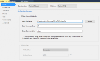
Select project-> properties, select use external makefile and select the Makefile file from the "mega328_st7565" directory, in the project directory.
In the Makefile file we change:
UI_LANGUAGE = LANG_ENGLISH on UI_LANGUAGE = LANG_POLISH (if we want Polish menu)
CFLAGS + = -DLCD_ST7565_H_OFFSET = 4 per CFLAGS + = -DLCD_ST7565_H_OFFSET = 0 (image shift)
CFLAGS + = -DLCD_ST7565_V_FLIP = 1 per CFLAGS + = -DLCD_ST7565_V_FLIP = 0 (vertical flip)
CFLAGS + = -DLCD_ST7565_H_FLIP = 1 per CFLAGS + = -DLCD_ST7565_H_FLIP = 0 (level reversal)
I also experimentally turned on:
CFLAGS + = -DWITH_UJT (Option WITH_UJT enables additional tests for UJT (UniJunction Transistor))
It's worth experimenting with the Makefile by reading the descriptions and documentation in \ Dock \ tags \ english
To generate files to be placed in the microcontroller's memory, select:
We choose Build-> Build Solution.
We should receive a message:
========== Build All: 1 succeeded, 0 failed, 0 skipped ==========
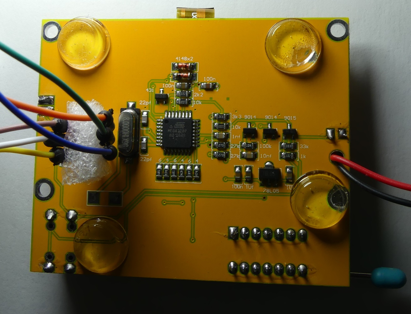
After completing the compilation, go to the "mega328_st7565" directory in the project directory, there is the TransistorTester.hex file (flash memory content) and TransistorTester.eep (eeprom content). Place both files in the memory of the ATMEGA328P microcontroller using the selected ISP programmer. I used AVRISP MKII and software from AtmelStudio environment. To connect to the ISP connector in the tester, I used the connecting cables for the contact plate. The photo below shows the pinout of the connector.
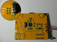
For the time of programming, we lock the button that turns on the device (e.g. with a clothes peg) to ensure continuous power supply of the microcontroller.
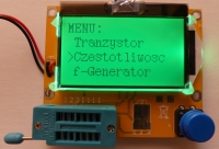
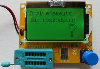
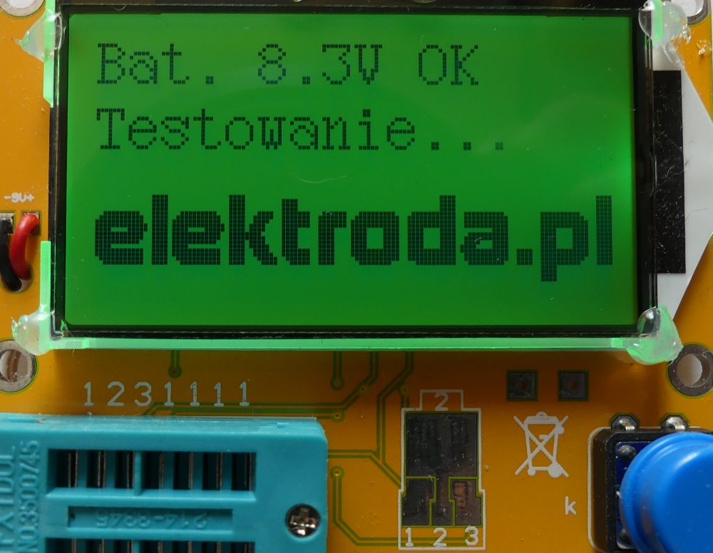
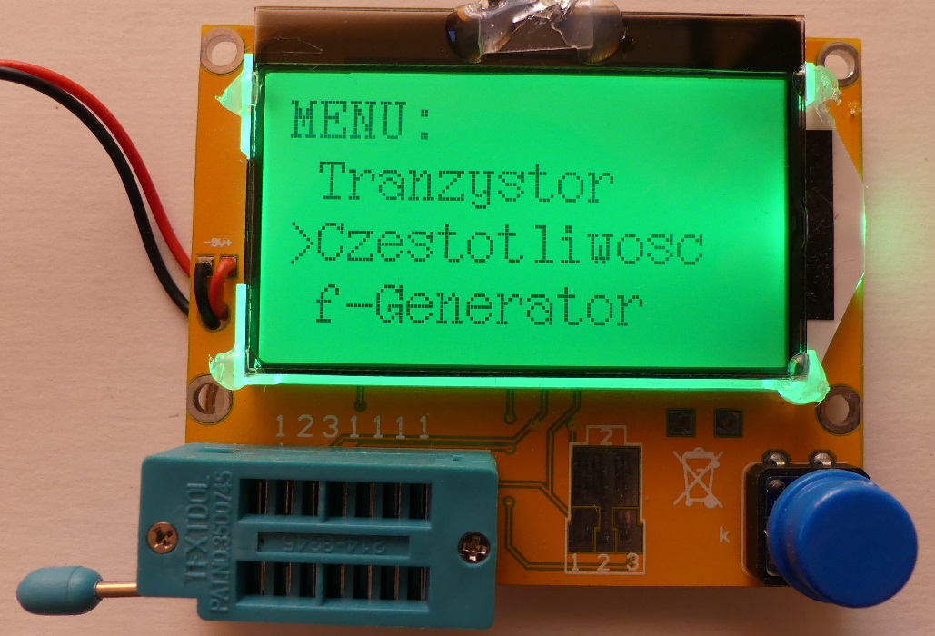
If everything goes well, the tester will greet us with messages in Polish:
 We put our own logo.
 Perhaps logo placement is not some super ambitious and necessary task, but it is a good way to start playing with tester code. We have an area of 128x32 black and white pixels at our disposal (during the ongoing test). We'll write each pixel as a bit in a byte, and that takes 512B in a 512-element array. Each byte will be a vertical 8-pixel dash starting at the top of the x-coordinate of the LSB bit of the array element. After reading as many elements as the image width is (in our example 128), we read the next bar at the y-greek coordinate by 8 pixels.
If we care about the logo and limit the memory consumption, we can think about a simple "compression", for example saving the coefficient of start and end lines horizontally or vertically instead of data for all pixels, for some pictures it will save memory.
The black and white elektroda.pl logo from the home page is saved to a PNG file with a resolution of 128x32:

With a simple python code, we convert a PNG file into an array, in which each bit corresponds to a lit or unlit pixel on the LCD. We set the height and width of the PNG file so that they are equal to the power of 2. For a 128x32 image we will have 128x (32/8) = 512 element array, a single element of the array will be a byte. To write the codes, we use the knowledge gained about python and png here:
Will the Sun clear the EPROM? Quickly written python 3 code will turn the PNG file into an array of bytes:
[syntax=python]from PIL import Image
i = Image.open("logo.png")
xx=i.width
yy=i.height
print("szerokosc: "+str(xx)+" wysokosc: "+str(yy))
if xx>128:
print("Szerokosc wieksza od 128, to nie zadziala...");
exit();
if yy>32:
print("Wysokosc wieksza od 32, to nie zadziala...");
exit();
if xx%2!=0 or yy%2!=0:
print("Szerokosc lub wysokosc nie jest potega 2, to moze nie zadzialac...");
data=i.load()
print("const unsigned char PROGMEM logo["+str(int(xx*(yy/8)))+"]= {") #rozpoczynamy tablice
for y in range(0,yy,8): #idziemy po wsp y obrazka
for x in range(0,xx): #idziemy po wsp x obrazka
b=0 #zerujemy wartosc bajt (wszystkie pixesle zgaszone)
for n in range(0,8): #sprawdzamy kolejne pionowe 8 pixeli na danej wsp. x
if y+n


Comments
I also got the impression that this software is worse at measuring transistors, thyristors, etc. But I would have to have a second tester with the original software to check it. As for the modifications,... [Read more]
Thanks for the description. In my free time I will test :) The "elektroda.pl" logo looks great and this is what the tester should look like from the very beginning, and the casing with the "elektroda.pl"... [Read more]
Stickers with the "elektroda.pl" logo were attached to the first series of the tester without the housing. Can be stuck to the housing and it will look better than the engraved inscription. [Read more]
Is it possible to copy the original program to the computer before changing the software? Something like a backup. [Read more]
If the microcontroller is protected against reading the program written in it, then there is no such possibility. [Read more]
I knew that much before writing the post ... I ask the author of the thread how it is in this case. [Read more]
Apparently the microcontroller is read-protected -> Link [Read more]
My T4 was not secured. If I manage to find my load. As for the "originality" of the firmware .. It is from https://www.mikrocontroller.net/svnbrowser/transistortester/ that is original ;) This is the... [Read more]
Maybe you could get one of the gadgets http://www.elektroda.pl/rtvforum/shop.php and compare? I also suspect that it is secured, I must admit that I forgot to check and make a copy, and maybe the... [Read more]
One that I have too few points to order - these points counted from 2015, probably two, it's a pity to take someone else since I already have such a tester. Someone has downloaded the original soft... [Read more]
Included the factory firmware for M328 from the electrode store (2nd batch of blue button) [Read more]
And since the topic about changing the firmware is due to the fact that my original display did not survive the assembly, I decided to adapt a 2x16 display to the existing board (popular HD 47780) Connection... [Read more]
An interesting way to deal with a display crash, what's the symbol after the number in the second line of the display? I did not expect that there is a description of the ISP connector on the other... [Read more]
As if someone was looking for the original display: https://www.gearbest.com/lcd-led-display-module/pp_530259.html [Read more]
Honestly, I have no idea what [RL] means, when connecting 1-2, it does not display this message Since these displays are such a lame, I preferred to make it more solid :) [Read more]
@ logos2000 I mean this symbol after the number 2162. [Read more]
Looking after a few resistors is a sign of ohms, but the fact that the ladder is strange, the firmware language is English. Edit. It turns out that this ladder was caused by the display, but at the... [Read more]
Here they boast with the software version V2.68: https://www.aliexpress.com/item/2016-V2-68-ESR-T4-Mega328-Digital-Transistor-Tester-Diode-Triode-Capacitance-ESR-Meter-MOS-PNP/32714478296.html I do not... [Read more]
True, apparently it is more accurate (it's hard to confirm it after one test), although the Registered badge on the project copied from the net is funny ... http://blog.goo.ne.jp/meg_8086/e/c42795fa1a6bbbd31f8c5102a806b70d ... [Read more]