logo elektroda
logo elektroda
X
logo elektroda
Dostępna jest polska wersja

Czy wolisz polską wersję strony elektroda?

Nie, dziękuję Przekieruj mnie tam

How to flash FL_M99_V1/FL_M99_V2/FL_M99_V3/CB2S WiFi module - BK7231N Tuya Home Assistant guide

p.kaczmarek2  0 4572 Cool? (+2)
📢 Listen (AI):

TL;DR

  • FL_M99_V1/FL_M99_V2/FL_M99_V3 WiFi modules use BK7231N/BL2028N and can be flashed with OpenBeken for basic Tasmota compatibility and Home Assistant features.
  • Their pinout appears to match CB2S, so you can flash them in circuit or after desoldering, using the BK7231GUIFlashTool or BK7231tool workflow.
  • The module provides 5 PWM outputs plus an ADC pin, which makes it suitable for RGBCW lighting and a light sensor.
  • CEN is not required for flashing here; a 3.3V power disconnect/reconnect cycle is used instead.
  • FL_M99_V1/FL_M99_V2/FL_M99_V3 seems flashable like CB2S, while FL_M93_V1 may be CB3S-compatible but remains unverified.
Summary generated by AI based on the discussion content.
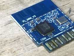
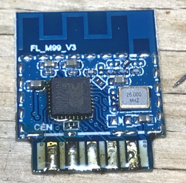
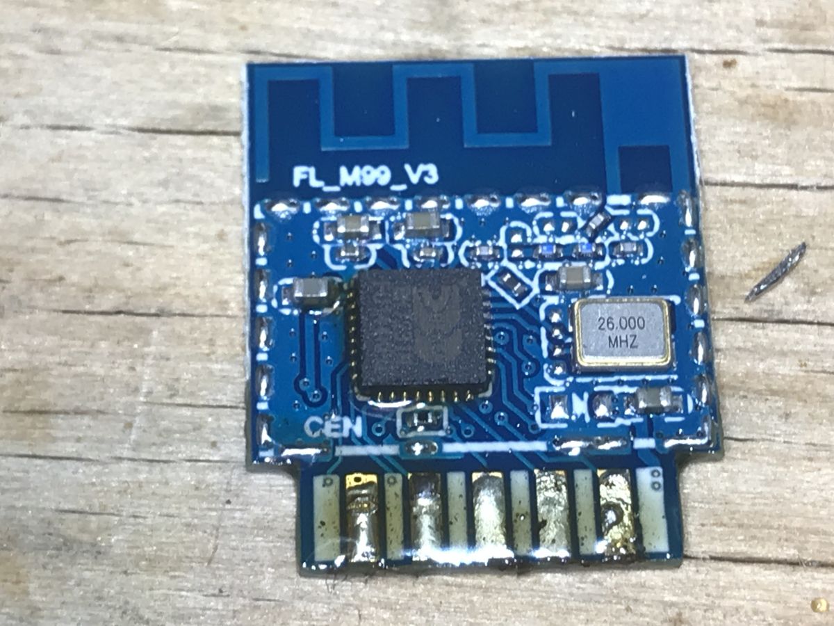
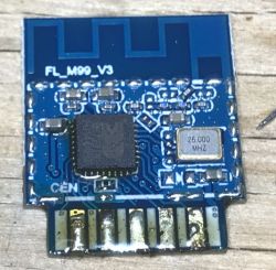
FL_M99_V3 module with a microcontroller on a blue PCB marked with 26.000 MHz.
Some of new Tuya IoT devices are based on FL_M99_V1/FL_M99_V2/FL_M99_V3 modules, which are using BK7231N/BL2028N WiFi 2.4GHz + Bluetooth microcontroller. They can be flashed with OpenBeken, which will provide basic Tasmota compatibility and Home Assistant features. Here's a basic FL_M99 pinout and flashing guide.

There have been already multiple reports of similiar modules on our forum, including:
- mini smart switch - Belon BL2028N
- Aubess 2gang Mini Smart Switch BK7231N /CB2S
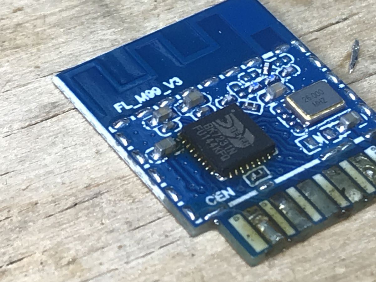
I have also received recently a WiFi smart switch based on FL_M99_V1, here is this module photo:
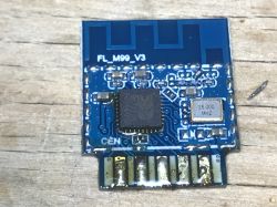
FL_M99_V3 IoT module on a wooden background Close-up of FL_M99_V3 module with BK7231N microcontroller. FL_M99_V1 electronic module with visible pins on a white casing.
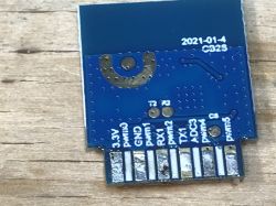
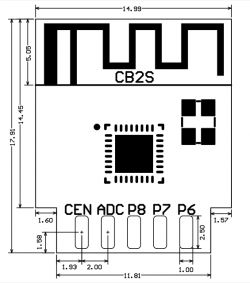
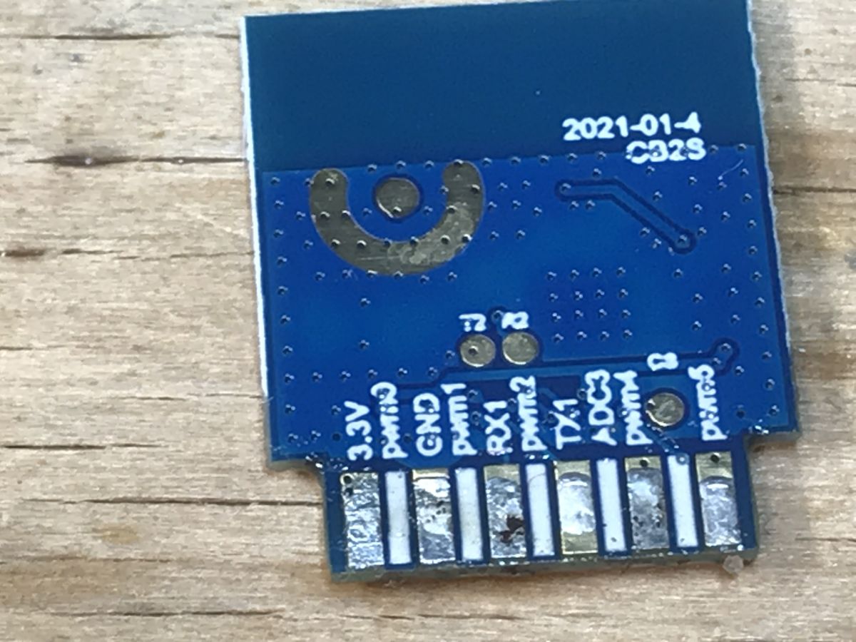
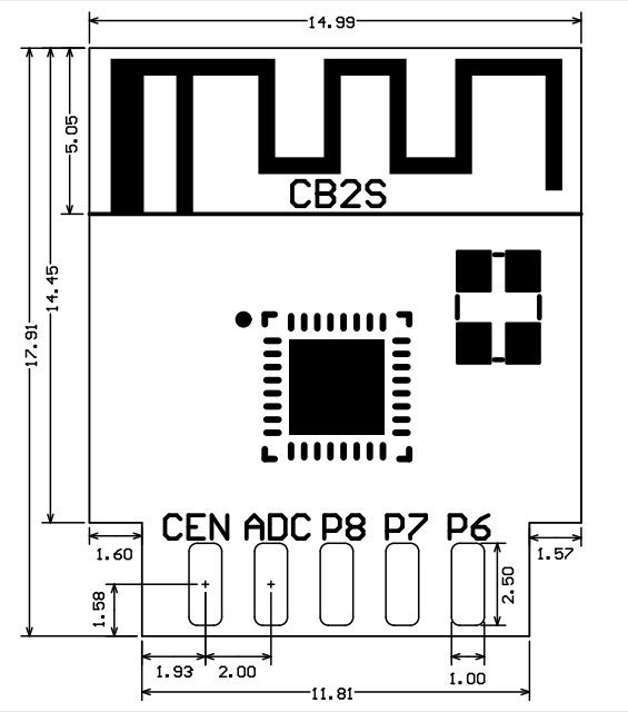
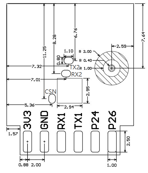
Module pinout seems to match CB2S:
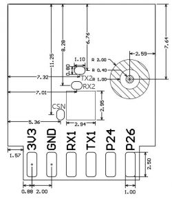
Technical drawing of the CB2S module with pin labels and dimensions.
Diagram of the FL_M99 module pin layout.
Pin numberSymbolI/O typeFunction
13V3PPower supply 3V3
2P6I/OSupport hardware PWM and correspond to P6 of the IC
3GNDPPower supply reference ground
4P7I/OSupport hardware PWM and correspond to P7 of the IC
5RX1I/OUART_RX1, which is used for receiving user data and corresponds to P10 of the IC. Do not pull it up. By default, the MCU serial port should be in low-level or high-impedance state.
6P8I/OSupport hardware PWM and correspond to P8 of the IC
7TX1I/OUART_TX1, which is used for transmitting user data and corresponds to P11 of the IC. Do not pull it up. By default, the MCU serial port should be in low-level or high-impedance state.
8ADCI/OADC, which corresponds to P23 of the IC
9P24I/OSupport hardware PWM and correspond to P24 of the IC
10CENI/OReset pin
11P26I/OSupport hardware PWM and correspond to P26 of the IC
Test pointRX2I/OUART_RX2, which corresponds to P1 of the IC. This pin is not allowed to use.
Test pointTX2I/OUART_TX2, which is used for outputting logs and corresponds to P0 of the IC
Test pointCSNI/OMode selection pin. If it is connected to the ground before being powered on, enter the firmware test mode. If it is not connected or connected to VCC before being powered on, enter the firmware application mode. It corresponds to P21 of the IC.

Availability of 5 PWM outputs makes this module suitable for RGBCW lighting, extra ADC pin can be also used for light sensor.


How to flash FL_M99_V1/FL_M99_V2/FL_M99_V3?
Flash it like CB2S, either in circuit, or desolder it from the board.
You can use our BK7231 flasher for that:
https://github.com/openshwprojects/BK7231GUIFlashTool
You can watch our old (hid_download_py) and new (BK7231tool flasher) guides:


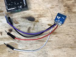
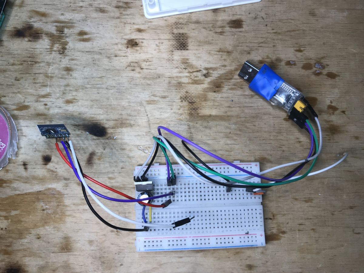
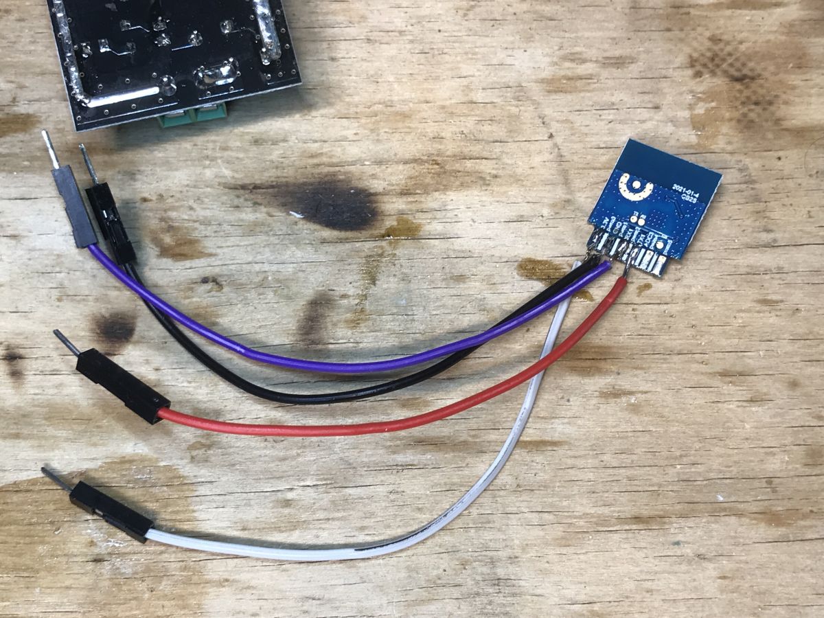
I am usually just desoldering the module, here is my setup:
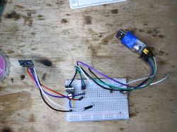
FL_M99 module connected to a breadboard with wires and a USB adapter. Orange FL_M99 module with attached wires on a wooden surface.
I do not solder CEN, I just do power on/off cycle by disconnecting and reconnecting 3.3V wire.

After flashing, you can refer to one of our many guides for BK7231 setup, including|:


Summary
FL_M99_V1/FL_M99_V2/FL_M99_V3 seems to be flashable just like CB2S. There also seems to be similiar modules, which are CB3S-compatible, for example FL_M93_V1, but I haven't checked it yet.
If you have encountered a device with this or similiar module, please make some photos and let us know. You can also make a teardown post and we'll submit it to our teardowns list

About Author
p.kaczmarek2
p.kaczmarek2 wrote 14684 posts with rating 12714 , helped 656 times. Been with us since 2014 year.

Comments

FAQ

TL;DR: With 5 PWM outputs, 1 ADC pin, and 3.3V serial flashing, FL_M99_V1/V2/V3 modules based on BK7231N or BL2028N can be flashed with OpenBeken; as the guide says, "flash it like CB2S". This helps Tuya smart-switch owners replace stock firmware and add Home Assistant-friendly control. [#20800227]

Why it matters: This FAQ gives a fast, extractable path for identifying, wiring, flashing, and configuring FL_M99-family Tuya modules without guessing pin roles.

Option Main use Method mentioned Practical note
FL_M99_V1/V2/V3 Target module family Flash like CB2S Reported as compatible for flashing
CB2S Reference-compatible module Same flashing approach Pinout appears to match FL_M99
FL_M93_V1 Similar but different family Compared with CB3S-style modules Not checked in the thread
In-circuit flashing Keep module on board Wire directly to module pads Board circuitry can complicate access
Desoldered flashing Remove module first Author’s usual method Easier standalone access

Key insight: The thread’s core takeaway is simple: treat FL_M99_V1, FL_M99_V2, and FL_M99_V3 as CB2S-style modules when flashing. The essential requirements are correct 3.3V, UART wiring, and proper CSN boot-mode handling. [#20800227]

Quick Facts

  • FL_M99 uses a 2.4GHz Wi‑Fi + Bluetooth MCU platform identified in the thread as BK7231N/BL2028N, and the module family discussed is FL_M99_V1/V2/V3. [#20800227]
  • The pinout includes 11 numbered pins plus test points; critical flashing pins are pin 1 = 3V3, pin 3 = GND, pin 5 = RX1, pin 7 = TX1, and pin 10 = CEN. [#20800227]
  • The module exposes 5 PWM-capable outputs on P6, P7, P8, P24, and P26, making it suitable for RGBCW lighting projects. [#20800227]
  • The ADC function is on pin 8 and maps to P23, which the thread highlights as useful for a light sensor input. [#20800227]
  • The CSN test point selects boot mode: connect it to ground before power-on for firmware test mode, or leave it open / tie it to VCC before power-on for application mode. [#20800227]

How do I flash an FL_M99_V1, FL_M99_V2, or FL_M99_V3 WiFi module with OpenBeken?

Flash it the same way as a CB2S module. 1. Connect a 3.3V serial setup to 3V3, GND, RX1, and TX1. 2. Put the module into the required mode and power-cycle it. 3. Use BK7231GUIFlashTool or the newer BK7231tool workflow to write OpenBeken. The guide also says you can flash it in-circuit or after desoldering, and the author usually removes the module first. [#20800227]

What is the pinout of the FL_M99 module, and which pins are used for 3.3V, GND, UART, CEN, and CSN during flashing?

The key flashing pins are pin 1 for 3V3, pin 3 for GND, pin 5 for RX1, pin 7 for TX1, and pin 10 for CEN. CSN is not a numbered edge pin; it is a test point used for mode selection. The thread also lists TX2, RX2, ADC, P24, and P26, but the essential UART path for flashing is RX1 and TX1 with a 3.3V supply. [#20800227]

What is OpenBeken, and how does it add Tasmota compatibility and Home Assistant features to BK7231N devices?

"OpenBeken is custom firmware that replaces Tuya software on BK7231-based devices, adds basic Tasmota compatibility, and exposes Home Assistant-oriented features." In this thread, it is presented as the firmware you flash onto FL_M99 modules built around BK7231N or BL2028N. Its value here is practical: it lets a Tuya smart switch move from stock cloud firmware to a more configurable local setup. [#20800227]

What is the CB2S module, and why is FL_M99 considered compatible with it for flashing?

"CB2S is a Tuya Wi‑Fi module family used as a flashing reference, because its pin layout and boot behavior match compatible BK7231-based boards." FL_M99 is considered compatible because the thread states its pinout seems to match CB2S and explicitly says to flash FL_M99_V1/V2/V3 like CB2S. That makes CB2S the practical baseline for wiring and flashing procedure. [#20800227]

Which flasher should I use for BK7231N or BL2028N modules: BK7231GUIFlashTool, hid_download_py, or BK7231tool?

Use BK7231GUIFlashTool if you want the tool directly recommended in the thread. The post links that tool first, then points to both an older hid_download_py guide and a newer BK7231tool flasher guide. That means the thread recognizes all three, but presents BK7231GUIFlashTool plus BK7231tool as the current practical path. [#20800227]

What is the difference between flashing an FL_M99 module in-circuit and desoldering it first?

In-circuit flashing keeps the module on the original board, while desoldering removes it for standalone access. The thread says both methods work, but the author states, “I am usually just desoldering the module,” and shows a separate setup photo. Desoldering gives clearer pad access and simpler power control, while in-circuit flashing avoids removal but depends on the surrounding board not interfering. [#20800227]

How do I put an FL_M99 or CB2S-style module into firmware test mode using the CSN pin?

Connect CSN to ground before power-on to enter firmware test mode. If CSN is left unconnected or tied to VCC before power-on, the module enters normal firmware application mode instead. That makes timing important: set CSN first, then apply power. The thread identifies CSN as the mode-selection test point and maps it to P21 of the IC. [#20800227]

Why should RX1 and TX1 on the FL_M99 module not be pulled up during flashing or normal use?

They should not be pulled up because the thread states both UART lines expect a low-level or high-impedance default state. RX1 is pin 5 and maps to P10, while TX1 is pin 7 and maps to P11. Pulling them up can break the intended serial behavior during flashing or normal communication. This is one of the clearest wiring limits in the pin table. [#20800227]

What does the CEN pin do on the FL_M99 module, and how can I reset or power-cycle the board without wiring CEN?

CEN is the reset pin on pin 10. You do not have to wire it if you can reset the board by cycling power instead. The author says, “I do not solder CEN,” and simply disconnects and reconnects the 3.3V wire to perform a power on/off cycle. That is the thread’s direct, working reset method for a desoldered setup. [#20800227]

How can I identify whether my Tuya smart switch uses FL_M99_V1, FL_M99_V2, FL_M99_V3, BK7231N, or BL2028N from board photos?

Check the module can marking and compare the pin layout with the FL_M99 photos and CB2S-style pinout shown in the thread. The post identifies the family by printed module names such as FL_M99_V1 and by the MCU platform named as BK7231N or BL2028N. Board photos that show the module top, pad layout, and nearby test points are the most useful for matching. [#20800227]

In what ways is FL_M99 similar to CB2S, and how does it compare with CB3S-compatible modules like FL_M93_V1?

FL_M99 is similar to CB2S because its pinout appears to match CB2S and the flashing method is stated to be the same. The thread contrasts that with FL_M93_V1, which is described only as a similar module that seems CB3S-compatible. The key limit is explicit: FL_M93_V1 had not been checked yet, so only FL_M99 gets a confirmed CB2S-style flashing recommendation here. [#20800227]

How do I configure a freshly flashed BK7231N-based FL_M99 device for Home Assistant after installing OpenBeken?

Use one of the BK7231 setup guides linked after flashing OpenBeken. The thread does not provide the full Home Assistant configuration steps inside the post, but it clearly says you can refer to several BK7231 setup guides after flashing. In practical terms, the post’s scope ends at successful flashing and then hands off to those setup resources for Home Assistant-oriented configuration. [#20800227]

What are the TX2, RX2, and CSN test points on the FL_M99 module used for?

TX2, RX2, and CSN are special test points rather than standard edge pins. TX2 outputs logs and maps to P0, RX2 maps to P1 and is marked “not allowed to use,” and CSN selects boot mode through power-on state. This creates one important edge case: RX2 exists physically, but the thread says not to use it. [#20800227]

How can the five PWM outputs and ADC pin on the FL_M99 module be used in RGBCW lighting or light sensor projects?

Use the five PWM-capable pins to drive five lighting channels, and use the ADC for sensor input. The thread explicitly says the module’s 5 PWM outputs make it suitable for RGBCW lighting, while the extra ADC pin can serve a light sensor. The PWM-capable signals listed are P6, P7, P8, P24, and P26, and the ADC is on pin 8 as P23. [#20800227]

What safety precautions and wiring checks should I follow when flashing a Tuya FL_M99 or CB2S WiFi module with a 3.3V serial adapter?

Use a 3.3V supply, confirm pin identity before powering, and avoid pulling up RX1 or TX1. 1. Verify pin 1 is 3V3 and pin 3 is GND. 2. Wire UART to pin 5 RX1 and pin 7 TX1. 3. Set CSN correctly before power-on if you need firmware test mode. The thread’s wiring warnings are specific: RX1 and TX1 should stay low or high-impedance by default, and CSN state determines boot mode. [#20800227]
Summary generated by AI based on the discussion content.
%}