logo elektroda
logo elektroda
X
logo elektroda

Atmega Fusebit Doctor (HVPP + HVSP) - fix fusebits

manekinen 261037 342
ADVERTISEMENT
Treść została przetłumaczona polish » english Zobacz oryginalną wersję tematu
  • #151 9815369
    mirekfd
    Level 11  
    Hello, I have a slightly "out of topic" question. The day before yesterday I was reprogramming the ATmega16 under the STK500 clone and with AVR Studio and it was not about 100,000 times, at most 50th when testing other versions of the software, it went about 20% and here suddenly an unexpected stop. The chip is no longer visible under the STK500. In this operation, nothing happened with the fusebits (I would not ask about such things), just uploading the batch.
    Thought to deal with it right now, I took out Chan's rarely used parallel programmer and checked that the ATmega16 chip was recognized. And unfortunately it wasn't. I had "Unknown device" under avrpp.exe. I thought that this scalak was for good. I took another out of the astatic box. And the same effect, ie "unknown device". The next two from the same box turned out to be good and reported correctly. I breathed a sigh that this is not a broken parallel programmer but something with systems. I went back to these two suspects again. unfortunately the programmer did not recognize them. The chips from the box were 100% OK, I tested them about 6 months back and put them back safely.

    After this lengthy description, I have a question. Has anyone had a similar case? Do you see any chance to revive these processors? What? Maybe it's some "watercourses" ... :-( ..... ???

    best regards

    mirekfd
  • ADVERTISEMENT
  • #152 9815402
    piotrva
    VIP Meritorious for electroda.pl
    Hmm, since the parallel programmer does not recognize ... it's a badly damaged processor ... Didn't some unexpected voltage on the board help them? Strange situation, with something like this I have never encountered ...
  • #153 9815605
    mirekfd
    Level 11  
    No, there were no unexpected tensions. The processor was sitting on the KAMAMI ZL3AVR prototype board all the time. It was a common time for the ISP to upload another test version of the software controlling the I2C expander.
    Previously, everything was going on, the change was only to test the change in the pattern of bits exposed to the port after a change in the tested program. The fuse bits were set up much earlier. I did not change the bit lock either. The power supply also did not fall unexpectedly, in a word, normal conditions.

    The fact that one of them fell, I can understand, but the other one was not sitting at all. I packed it in working order, it left off for half a year and now I took it out of the box for a replacement and it immediately went to the parallel programmer and ..... the flap, like the one from the prototype board. Now I have two out of four. Some "fate" ??

    mirekfd
  • #154 9816562
    manekinen
    Level 29  
    I would bet on some overvoltage, connecting an unearthed computer to the USB, some ESD from the carpet, etc. Because such a sudden death is not a normal matter. Look for your mistakes before the rest fail.

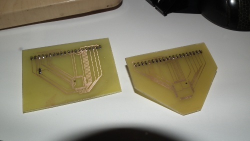
    // added

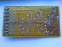
    I finally repaired the printer and was able to make the adapter ... soldering these vias is a massacre, but it will definitely pay off ;)
    Atmega Fusebit Doctor (HVPP + HVSP) - fix fusebits
  • ADVERTISEMENT
  • #155 9922587
    novak512
    Level 12  
    Hello,
    I did the doctor but ran into one serious problem.
    Project version is 2.11, controlling atmega8 programmed with avr burn o mat, fuski uC is l: E1; h: D1. I concluded that in this version you do not need to upload an older eeprom file. As a doctor I used 3 different (working) atmega, but the problem remains. Basically, I can't save / edit fuse bits (I can edit lock bits). I tried again for 2 atmeg8 and 2 of 2313 and the effect is the same. Below are the logs from the terminal for 2 atmeg8.

    MANUAL HVPP MODE
    Init programming ... DONE
    Read signature ... 1E 93 07
    Searching chip ... no names in 8kB ver
    Read fusebits ... L: C8 H: E0 E: 00
    Should be ... L: E1 H9 E: 00
    Lockbits ... DISABLED (FF)

    Chip erase ... DONE

    Writing E1 D9 00 ... DONE
    Verifying ... L: FF H: FF E: 00- FAIL!
    Please try again ...
    -------------------------------------------------- -

    MANUAL HVPP MODE
    Init programming ... DONE
    Read signature ... 1E 93 07
    Searching chip ... no names in 8kB ver
    Read fusebits ... L: 1B H: E0 E: 00
    Should be ... L: E1 H9 E: 00
    Lockbits ... DISABLED (FF)

    Chip erase ... DONE

    Writing E1 D9 00 ... DONE
    Verifying ... L: FF H: FF E: 00- FAIL!
    Please try again ...
    -------------------------------------------------- -

    What could be causing the wrong operation?
    I would like to ask for a small hint on how to solve this problem.
  • ADVERTISEMENT
  • #156 9922765
    manekinen
    Level 29  
    Okay, tell me if the fuselage values read after initialization are true?

    I mean L: C8 H: E0 E: 00 and L: 1B H: E0 E: 00

    Quite a strange thing is the FF on the second read (after writing).

    Are the + 12V and + 5V voltages correct? There were situations that the reset voltage was too low or the times of its application / forbidden did not match and the doctor communicated with the system in parallel but he could not change the leaves.

    Also check the quality of the assembly carefully, but with the meter - because this is often the cause of trouble ... the system can read the signature but not necessarily write what is needed or where it is needed - address lines and command lines may have, for example, cold February.

    The coffee grounds settings are correct, you don't even need to touch them for the system to work. Since it spits the log on the terminal, the program is also correctly uploaded. Eeprom does not need to be uploaded, it was only in one of the older versions.
  • #157 9990802
    novak512
    Level 12  
    Hello, after such a long break. :) The academic year has started, so it is time for a little self-education. :P

    The doctor has finally been launched. The error that caused him not to act was, of course, a short circuit on the DATA5 line. I tried to write down the different coffee grounds on the working machines and then compare them with those from the doctor. It turned out to be reading lfuse correctly, while hfuse was wrong.
    The short circuit was so slight that I found it only after painstakingly checking the short circuit between the patient lines with a meter.

    I managed to unlock 2 atmegi8s, but I ran into a problem with the remaining 2 atmegi8s and 3x 2313. In both cases everything indicates that their signature is damaged. Is it possible for such a large amount of uC to be defective?

    log for AT2313:
    Init programming ... DONE
    Read signature ... FF FF FF - FAIL!
    Trying T2313 pinout..FF FF FF - FAIL!
    Type the signature: 1E910A
  • #158 9990884
    manekinen
    Level 29  
    Hello. It's nice that the error was found :)

    A damaged signature is beyond repair. No programmer will do it, it's Atmel's secret how they write these signatures :) If this information leaked out and it was possible to do it at home, think how many painted layouts would hit the market ...

    So these tiny2313 are working, but to be able to communicate with them from avrdude you have to use the option -F which will skip reading the signature.

    As for atmeg8 - in my opinion they are dead.

    I would like to remind you that I have tiles for this layout, if someone has a problem with making their own (and it is a bit dense), then I invite you. I soldered my circuit to the factory PCB :)
    Atmega Fusebit Doctor (HVPP + HVSP) - fix fusebits Atmega Fusebit Doctor (HVPP + HVSP) - fix fusebits
  • #159 9997272
    zdarecki
    Level 12  
    Hello,
    finally I mobilized myself and put together this system in the smd version.
    tile patterns in pdf after printing are smaller, I adjusted by enlarging in the printer settings - 100.5%
    the system practically takes off from the first shot there were no problems

    2 atmegi8 in a DIP housing were up, it was supposed to be great ;)
    while in the smd housings (of course a different adapter) I had 2 atmegi16 and 3 atmegi8 blocked (mainly I was counting on them) and the defeat of the fusia cannot be changed.
    It drove me to connect a working atmeg8 ... and it joined the scrap box.

    I would think that these atmegs are completely blown (they were all blown with kontrollerlab, I discovered such a bug in it), but why did it break out efficiently?
    I checked the adapter, there are no gaps, no short circuits, what is it?

    I modified the programmer to version 2.11 but the manual option did not bring anything new.

    best regards
  • #160 9997584
    manekinen
    Level 29  
    Write more details. What LED is on? Such a thing is due to the fact that one of the smd adapter pads does not connect and thus the fuses transferred to the prock are wrong. Try to align the pads and / or apply more pressure to the pads.

    You write that the manual option does not help, that is, your system is connected to the terminal ... What does the terminal say? What are the fuses after saving? It's best to paste some logs.
  • #161 9997849
    zdarecki
    Level 12  
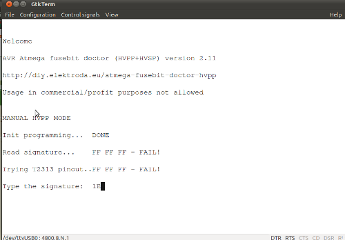
    LEDs in auto mode: briefly lights up green then flashes red
    below adds a screenshot from manual mode

    Atmega Fusebit Doctor (HVPP + HVSP) - fix fusebits
  • #162 9999373
    manekinen
    Level 29  
    There must be some babol on the board though.
  • ADVERTISEMENT
  • #163 10002037
    zdarecki
    Level 12  
    I have no idea what this adapter does not suit, but I know 100% that it's his fault.
    I made a single adapter for the atmega16 and one of them got up, the other stopped showing signs of life.
    there is progress, so I carve the adapter for atmegi8

    edit:
    Live atmega on new adapters, with the exception of 1 pc. atmegi16, but I guess I finished it when correcting the adapter without disconnecting it from the programmer.

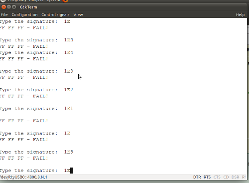
    However, I do not know if it is just for me or it is a shortcoming of the program, if there is a problem with reading the signature, the program hangs and leaves 12v on at the reset
    I enclose the screen
    Atmega Fusebit Doctor (HVPP + HVSP) - fix fusebits

    and these are the adapters that worked for me
    Atmega Fusebit Doctor (HVPP + HVSP) - fix fusebits

    best regards
  • #164 10004175
    manekinen
    Level 29  
    Hmm, I don't remember what it was like, I will check the program when I come back from work :) But he should disconnect both voltages correctly so that the system can be safely removed.

    And the 5V power supply is also not disconnected?
  • #165 10004396
    zdarecki
    Level 12  
    In the manual mode, both voltages remain on, and in the automatic unit it is as if the program continues because it turns off the voltage and the red LED lights up.
  • #166 10004564
    manekinen
    Level 29  
    Oh, which is good. In the manual mode, it does not release the voltage, but waits for the signature to be entered, the procek is still in the programming mode until we choose the "5 - end" option. The machine does its job and ends by itself.
  • #167 10004590
    zdarecki
    Level 12  
    You can not choose any option, on the screen you can see that he is entering the numbers after 1E, I approve enter but it does not matter the program does not end and both voltages remain on

    screen
    Atmega Fusebit Doctor (HVPP + HVSP) - fix fusebits
  • #168 10004612
    manekinen
    Level 29  
    Because you have to enter the signature to go further (the correct signature) ... hmm, in fact, there would be a handy option to cancel or something. Unfortunately, I do not plan to issue further updates because it looks like the program works flawlessly (nobody reports anything), but if necessary, I will remember about it :)
  • #169 10004654
    zdarecki
    Level 12  
    It works OK, but you have to be careful about it every time you fix the prock in the adapter, which in turn is a bit tedious.

    Procki raised, thanks for the cool programmer.

    best regards
  • #170 10039231
    karel21
    Level 28  
    Are any changes necessary when using the Atmega 8L-8AI as a doctor? Does it also matter which atmega I put in, as long as it is Atmega 8.
  • #171 10039239
    manekinen
    Level 29  
    It does not matter - you upload the batch for atmega8 and that's it. Same with the coffee grounds. I suggest you read about the differences between these versions :)
  • #172 10039291
    karel21
    Level 28  
    Yes, I know it is smd, I have a dozen or so of them, I want to use them. :D .
  • #173 10150562
    gaspaccio
    Level 20  
    A really useful project. I took advantage and built my copy.
    However, I encountered a problem, in the diagram the resistors on the signal lines have a value of 1k, which in my case resulted in the inability to write.
    Changing to 470ohm helped.
  • #174 10151248
    manekinen
    Level 29  
    Is my friend the same person who wrote this on my website? If not, we already have two cases.

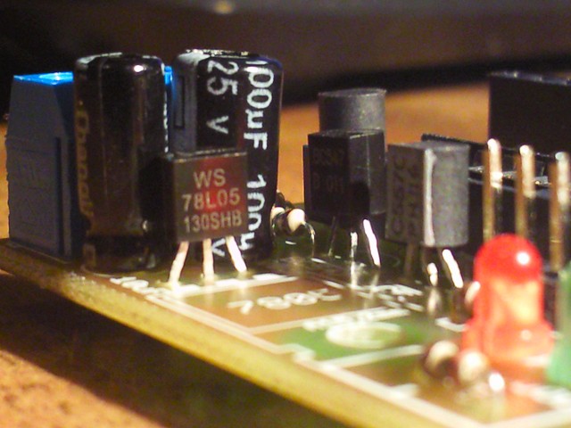
    And today, during the assembly, I tested the system with the 78L05 stabilizer - the version in the TO92 housing, max current 100mA. It is doing great, the current does not exceed 70mA (circuit assembled according to the diagram). It can also be successfully used interchangeably, it is cheaper, and it is enough to solder it like this:

    Atmega Fusebit Doctor (HVPP + HVSP) - fix fusebits
  • #175 10314209
    norbus2000a
    Level 14  
    Is it possible to buy a ready-made project (board, elements, etc.) for self-assembly?
  • #176 10314596
    piotrva
    VIP Meritorious for electroda.pl
    http://diy.elektroda.eu/sklepik/
    The PCB - no problem, as for the parts, they are so basic that you can buy in a random electronic one. Relatively, one can ask Kol. Manekinen about a programmed mega8.
  • #177 10314783
    norbus2000a
    Level 14  
    I can program AVRs! I'll buy the parts. I meant the plate! I'm thin at this :)
  • #178 10372309
    ediko
    Level 2  
    Hello!
    I have a problem with the ATmega 644AP-PA, is there anything else to do with it?
    I checked Doctor but he did nothing, in the same socket Atmange32 changed the settings (so it seems to be working).
    The 644PA cannot change the fusebits, the 644PA can be properly erased and programmed, except for the programming and verification of the bootloader.

    Message from avrdude:
    avrdude: verifying ...
    avrdude: verification error, first mismatch at byte 0 × 0000
    0xff! = 0x15
    avrdude: verification error; content mismatch
    avrdude: safemode: Fuses OK
    avrdude done. Thank you.

    The rest will be explained in the Doctor screenshot:
    AVR Atmega fusebit doctor (HVPP + HVSP) version 2.11 "- 2H PCB
    http://diy.elektroda.eu/atmega-fusebit-doctor-hvpp
    Usage in commercial / profit purposes not allowed
    Read signature ... 1E 96 0A "
    MANUAL HVPP MODE
    Init programming Searching chip... no names in 8kB ver
    Read fusebits... L: EF H: 91 E: FD
    Should be... L: 62 H: 99 E: FF
    Lockbits... DISABLED (FF)

    Manual setting of fusebits
    Type fuse LOW: 62
    Type fuse HIGH: 99
    Type fuse EXTENDED: ff
    Writing 62 99 FF... DONE
    Verifying... L: EF H: 91 E: FD- FAIL!
    Please try again...

    There is a note on the fusecalca side of this processor, but I don't understand what's going on.
  • #179 10374089
    manekinen
    Level 29  
    This note concerns the unused (non-existent) bits in fusia that should default to "1", but that this is not always the case. Well, I haven't seen an unused bit read as "0" yet, but I've encountered a situation where different programmers could read it their own way and eggs came out.

    Fuse doctor in its database, default fuses are written in accordance with the note, ie unused bits are always treated as "1". If you try to enter zeros while editing the grounds manually, the verification will crash because they will be read as "1".

    ediko wrote:
    The 644PA can be properly erased and programmed, except for bootloader programming and verification.

    I mean we are talking about programming and verification? The "normal" part of flash works normally, but the bootloader part is not? Can you not change these grounds with an ordinary programmer? Hmm, the layout may be damaged :( I know cases that the memory content simply "froze", the system could work with the current content, but it was not possible to change the flash or the chips. It is somehow strange here.
  • #180 10375799
    ediko
    Level 2  
    The problem solved itself - after a few experiments with deleting and programming the processor actually "froze" - it remained on the last uploaded file.

Topic summary

The discussion revolves around the Atmega Fusebit Doctor, a device designed to repair misconfigured fuse bits in AVR microcontrollers, particularly the Atmega series. Users share their experiences with the device, detailing issues such as incorrect fuse settings, inability to read signatures, and challenges in programming various Atmega models. Solutions include using the device to reset fuse bits, ensuring proper connections, and troubleshooting with UART communication. The conversation highlights the importance of correct voltage levels, resistor values, and the need for careful assembly to avoid short circuits. Users also discuss the potential for using the device with different AVR models and the necessity of firmware updates for compatibility.
Summary generated by the language model.
ADVERTISEMENT