logo elektroda
logo elektroda
X
logo elektroda

Atmega Fusebit Doctor (HVPP + HVSP) - fix fusebits

manekinen 259633 342
ADVERTISEMENT
Treść została przetłumaczona polish » english Zobacz oryginalną wersję tematu
  • #181 10481706
    endru666
    Level 10  
    Hello,
    I am using Fusebit Doctor version 2.11 together with a board dedicated to this version of the software. As a doctor, I use uC atMega8L.
    However, when I try to repair another atMegi8 in the terminal, I get something like this:
    
    a fusebit doctor (HVPP+HVSP) version 2.11
    http://diy.elektroda.eu/atmega-fusebit-doctor-hvpp
    Usage in commercial/profit purposes not allowed
    
    MANUAL HVPP MODE
    
    Init programming...  DONE
    Read signature...    00 00 02 - FAIL!
    Trying T2313 pinout..00 00 02 - FAIL!
    Type the signature:  1E


    I understand that the program cannot read the signature and waits to provide it, so I give it and receive it:
    a fusebit doctor (HVPP+HVSP) version 2.11
    http://diy.elektroda.eu/atmega-fusebit-doctor-hvpp
    Usage in commercial/profit purposes not allowed
    
    MANUAL HVPP MODE
    
    Init programming...  DONE
    Read signature...    00 00 02 - FAIL!
    Trying T2313 pinout..00 00 02 - FAIL!
    Type the signature:  1E9307


    and the program is standing.
    I have no ideas how to move it.
    Maybe someone has already encountered such a problem.
    Finally, I will add that the HVPP jumper is still on.
  • ADVERTISEMENT
  • #182 10482448
    manekinen
    Level 29  
    After entering the signature, press enter. If this does not help, check the terminal settings or use another one, the terminal must send a carriage return after pressing this button, then the program will continue.

    And the read signature "00 00 02" suggests that there are some errors on the board :) Is the repaired atmega functional or unknown?
  • ADVERTISEMENT
  • #183 10486952
    endru666
    Level 10  
    Hello,
    In fact, after typing the signature, enter was missing, I changed the terminal to putty and it's good.
    I also found a short circuit on the data bus - corrected and it is much better, however still Fusebit Doctor cannot change the grounds.
    In the terminal it looks like this:
    
    Welcome
    AVR Atmega fusebit doctor (HVPP+HVSP) version 2.11
    http://diy.elektroda.eu/atmega-fusebit-doctor-hvpp
    Usage in commercial/profit purposes not allowed
    
    MANUAL HVPP MODE
    
    Init programming...  DONE
    Read signature...    1E 1E 07 - FAIL!
    Trying T2313 pinout..1E 1E 07 - FAIL!
    Type the signature:  1E9307
    
    Searching chip...    no names in 8kB ver
    Read fusebits...     L:07 H:A2 E:00
    Should be...         L:E1 H:D9 E:00
    Lockbits...          ENABLED  (A2)
    
    What to do?...
    1 - write fusebits
    2 - modify fusebits
    3 - set lockbits
    4 - chip erase
    5 - end
    
    Chip erase...        DONE
    
    What to do?...
    1 - write fusebits
    2 - modify fusebits
    3 - set lockbits
    4 - chip erase
    5 - end
    
    Writing E1 D9 00...  DONE
    Verifying...         L:07 H:A2 E:00- FAIL!
    Please try again...
    
    What to do?...
    1 - write fusebits
    2 - modify fusebits
    3 - set lockbits
    4 - chip erase
    5 - end
    
    Thank You


    What could be wrong now?
  • ADVERTISEMENT
  • #184 10492639
    lucastg
    Level 14  
    Hello, I have a question how to set the fuse for the atmega 8 for the 1st version of the software so as not to block it, of course ;) , I guess that the internal resonator is probably 8 Mhz and something else?
  • #185 10508223
    manekinen
    Level 29  
    endru666 wrote:
    What could be wrong now?

    Still bugs on the board. The signature must be read well. There is no point in typing it by hand. And the more so 1E 1E 07 it's almost Atmega8 :)

    lucastg wrote:
    for the 1st version of the software

    And why a friend of this old version of the mushroom?
  • #186 10530458
    kaeltaz
    Level 16  
    Hello, I would like to know what happens when the doctor is connected to the power supply, should the red LED light up? Because I do not have any light, only when I touch the plate from the bottom, in the place of the doctor's signal lines, the red LED lights up. I will also post logs after connecting the terminal.
    After switching on:
    Quote:
    Welcome
    AVR Atmega fusebit doctor (HVPP + HVSP) version 2.11
    http://diy.elektroda.eu/atmega-fusebit-doctor-hvpp
    Usage in commercial / profit purposes not allowed

    MANUAL HVPP MODE

    Init programming ...


    after touching the tile:
    Quote:
    Welcome
    AVR Atmega fusebit doctor (HVPP + HVSP) version 2.11
    http://diy.elektroda.eu/atmega-fusebit-doctor-hvpp
    Usage in commercial / profit purposes not allowed

    MANUAL HVPP MODE

    Init programming ... DONE
    Read signature ... 00 01 02 - FAIL!
    Trying T2313 pinout..00 01 02 - FAIL!
    Type the signature: 1E


    after putting attina2313
    Quote:
    Welcome
    AVR Atmega fusebit doctor (HVPP + HVSP) version 2.11
    http://diy.elektroda.eu/atmega-fusebit-doctor-hvpp
    Usage in commercial / profit purposes not allowed

    MANUAL HVPP MODE

    Init programming ... DONE
    Read signature ... FF FF FF - FAIL!
    Trying T2313 pinout..1E 91 0A
    Searching chip ... no names in 8kB ver
    Read fusebits ... L: EF H :D FE: FF
    Should be ... L: 64 H :D FE: FF
    Lockbits ... DISABLED (FF)

    What to do? ...
    1 - write fusebits
    2 - modify fusebits
    3 - set lockbits
    4 - chip erase
    5 - end

    The system uses 78mA dry, I use atmegi8a-pu.
  • ADVERTISEMENT
  • #187 10535255
    manekinen
    Level 29  
    How would you like to initiate programming with NO chip inserted? You touch the RDY line, which the doctor reads as patient readiness. It is normal that the line is not tucked up. The LEDs show the result, not e.g. readiness.
  • #188 10535883
    kaeltaz
    Level 16  
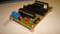
    OKAY. Thanks for the explanation, now everything is clear. It will also show a modified plate with 4 mounting holes and a 7805L stabilizer.
    Atmega Fusebit Doctor (HVPP + HVSP) - fix fusebits
  • #189 10539433
    manekinen
    Level 29  
    Very nice, you can throw in your tile design, maybe someone will use it :)

    And as for the power consumption - It all goes to the 100ohm resistor pulling the 12V line. You can use a larger value for this and the current will drop, but I guess it's not that terribly much, it's important that it works :)
  • #191 10761396
    mcgusto
    Level 13  
    Question, can the new version unlock LOCK bits in Atmega64 or 128? without losing flash and eeprom ??? I have built a layout but I have lost the contents :(
  • #192 10761558
    piotrva
    VIP Meritorious for electroda.pl
    Unfortunately, lockbits cannot be ("in a human way") unlocked without deleting all memory of the processor. The only possibility is to find someone who reverse engineers microcontrollers and knows how to "disassemble" the processor into preliminary parts ;-)
    So if you don't have a LOT of excess money, you can say goodbye to the batch ;-)
  • #193 10772559
    wojtekm97
    Level 10  
    Hello! I made a doctorate on my own PCB, connected it via rs232 and tried to unlock the Atmega8 and 16, but something is wrong.
    the voltage of 5V and 12V comes in nicely when pressing the button.
    After pressing "START" the green diode flashes 2 times quickly and the red diode lights up and the following log from the terminal pops up:
    
    Welcome
    AVR Atmega fusebit doctor (HVPP+HVSP) version 2.11
    http://diy.elektroda.eu/atmega-fusebit-doctor-hvpp
    Usage in commercial/profit purposes not allowed
    
    AUTOMATIC HVPP MODE
    
    Init programming...  DONE
    Read signature...    3E 3F 03 - FAIL!
    Trying T2313 pinout..1E 14 03 - FAIL!
    
    No chip in socket or chip does not responding
    
    Please try again...
    
    Thank You


    and from time to time the signature value changes there:

    Read signature...    1E 14 03 - FAIL!
    Trying T2313 pinout..1E 14 03 - FAIL!


    The same is on Atmega16 and 8. As for the sixteen I'm not sure if she's alive, but the eight is definitely functional because she wears a watch every day :)

    I gave 1K resistors on the PCB, and the author said that it is better to give 330Ohm, but I didn't listen. Can they cause these errors? Maybe the numbers at the signature say something more specific?
    I hope someone will advise me on something :)
    I greet and wish you a Merry Christmas :)

    EDIT: I checked the RESET and 5V voltage again, and the 5V idle state is 0.5V so maybe is it too high?
  • #194 10774371
    manekinen
    Level 29  
    You have initialized the process, so the voltage is ok. The signature says you have errors on pcb.
  • #195 10777212
    wojtekm97
    Level 10  
    That's right! The Doctor is already flashing! :)
    There was a micro-intersection that I noticed only under 2 magnifying glasses!
    Additionally, I refreshed all February so it could help as well :)
    Thank you very much :)
  • #196 10947667
    paluch_gda
    Level 16  
    I decided to build this gem, but I'm already hitting on something. At first, after turning on the power, both LEDs were on. Now it is so that after turning on, both will flash probably 4 times and silence. The same after the reset. Do you have any advice on this. Where to look because I have run out of ideas. I have x-rayed the plate several times and I do not see any surprises on it.

    And yet there were some breaks in the paths. if

    Welcome
    AVR Atmega fusebit doctor (HVPP + HVSP) version 2.11
    http://diy.elektroda.eu/atmega-fusebit-doctor-hvpp
    Usage in commercial / profit purposes not allowed

    AUTOMATIC HVPP MODE

    Init programming ... DONE
    Read signature ... 00 01 02 - FAIL!
    Trying T2313 pinout..00 01 02 - FAIL!

    No chip in socket or chip does not responding

    Please try again ...

    Thank You

    is no communication on data buses?
    [/ code]

    pins corrected and one atmega gave the answer

    elcome
    AVR Atmega fusebit doctor (HVPP + HVSP) version 2.11
    http://diy.elektroda.eu/atmega-fusebit-doctor-hvpp
    Usage in commercial / profit purposes not allowed

    AUTOMATIC HVPP MODE

    Init programming ... DONE
    Read signature ... 1E 93 07
    Searching chip ... no names in 8kB ver
    Chip erase ... DONE
    Read fusebits ... L: E1 H :D 9 E: 00
    Should be ... L: E1 H :D 9 E: 00
    Lockbits ... DISABLED (FF)
    Writing E1 D9 00 ... DONE
    Verifying ... L: E1 H :D 9 E: 00 - OK!
    2 fixed chips

    but the rest

    elcome
    AVR Atmega fusebit doctor (HVPP + HVSP) version 2.11
    http://diy.elektroda.eu/atmega-fusebit-doctor-hvpp
    Usage in commercial / profit purposes not allowed

    AUTOMATIC HVPP MODE

    Init programming ... DONE
    Read signature ... 9E 93 87 - FAIL!
    Trying T2313 pinout..9E 93 87 - FAIL!

    No chip in socket or chip does not responding

    Please try again ...

    does that mean they are dead?

    besides, how do I force the terminal to enter the signature?
  • #197 11353472
    albion1
    Level 17  
    kaeltaz wrote:
    Please, I am posting a modified pcb pattern.

    Ground power path seems to be missing and some paths are hanging in the air.
  • #198 11365462
    manekinen
    Level 29  
    The basics of eagle handling. After loading, click "ratsnest" :)
  • #199 11417992
    albion1
    Level 17  
    Przy próbie wgrania pliku wyskakuje mi błąd. Atmega8 sprawna. Co robie źle ?


    C:\WinAVR-20100110\bin\avrdude.exe -C C:\WinAVR-20100110\bin\avrdude.conf -p m8 -P /dev/parport0 -c usbasp -U eeprom:w:C:\Users\pawel\Desktop\atmega-hvpp-fusebit-doctor_update11\firmware\Atmega8\atmega_fusebit_doctor_2.11_m8.hex:a

    avrdude.exe: AVR device initialized and ready to accept instructions

    Reading | ################################################## | 100% 0.01s

    avrdude.exe: Device signature = 0x1e9307
    avrdude.exe: reading input file "C:\Users\pawel\Desktop\atmega-hvpp-fusebit-doctor_update11\firmware\Atmega8\atmega_fusebit_doctor_2.11_m8.hex"
    avrdude.exe: input file C:\Users\pawel\Desktop\atmega-hvpp-fusebit-doctor_update11\firmware\Atmega8\atmega_fusebit_doctor_2.11_m8.hex auto detected as Intel Hex
    avrdude.exe: ERROR: address 0x0210 out of range at line 33 of C:\Users\pawel\Desktop\atmega-hvpp-fusebit-doctor_update11\firmware\Atmega8\atmega_fusebit_doctor_2.11_m8.hex
    avrdude.exe: write to file 'C:\Users\pawel\Desktop\atmega-hvpp-fusebit-doctor_update11\firmware\Atmega8\atmega_fusebit_doctor_2.11_m8.hex' failed

    avrdude.exe done. Thank you.
  • #200 11419814
    manekinen
    Level 29  
    Something wrong with the HEX file. Something changed it? Please try to download again.
  • #201 11421496
    albion1
    Level 17  
    I downloaded a new HEX file, even tried to upload older versions and then the same. Replacing the new atmega8 also did not help.
  • #202 11422251
    manekinen
    Level 29  
    Uploads other batches correctly? Maybe avrdude in some strange / unofficial / old version?
  • #203 11424367
    albion1
    Level 17  
    The same error crashes with other batches.
  • #205 11511604
    manekinen
    Level 29  
    Thanks. Have all the mentioned systems been tested on it?
  • #207 11512332
    Mich43l
    Level 20  
    Hello, my friend blocked atmege32 by setting one of the fusebits, but he doesn't remember which one, is this project able to help me? (Atmega not responding while reading / writing)
  • #208 11512398
    djoy
    Level 15  
    Quote:
    Hello, my friend blocked atmege32 by setting one of the fusebits, but he doesn't remember which one, is this project able to help me? (Atmega not responding while reading / writing)


    YES :D
  • #209 11512445
    Mich43l
    Level 20  
    I understand that depending on the blocked chip, you need to upload another repair program to atmega8?
  • #210 11512642
    djoy
    Level 15  
    NO, the "repair program" is one for all CPUs mentioned by the author at the beginning of this topic ...

Topic summary

The discussion revolves around the Atmega Fusebit Doctor, a device designed to repair misconfigured fuse bits in AVR microcontrollers, particularly the Atmega series. Users share their experiences with the device, detailing issues such as incorrect fuse settings, inability to read signatures, and challenges in programming various Atmega models. Solutions include using the device to reset fuse bits, ensuring proper connections, and troubleshooting with UART communication. The conversation highlights the importance of correct voltage levels, resistor values, and the need for careful assembly to avoid short circuits. Users also discuss the potential for using the device with different AVR models and the necessity of firmware updates for compatibility.
Summary generated by the language model.
ADVERTISEMENT