logo elektroda
logo elektroda
X
logo elektroda

Atmega Fusebit Doctor (HVPP + HVSP) - fix fusebits

manekinen 259630 342
ADVERTISEMENT
Treść została przetłumaczona polish » english Zobacz oryginalną wersję tematu
  • #241 13220647
    enterrupter
    Level 12  
    Hello, I have a problem with the atmega 2560, does anyone know how to make an adapter for fusebit repair for it?
  • ADVERTISEMENT
  • #242 13220697
    manekinen
    Level 29  
    enterrupter wrote:
    Hello, I have a problem with the atmega 2560, does anyone know how to make an adapter for fusebit repair for it?
    Yes. Note of your microcontroller, chapter "memory programming"> "parallel programming". You have described the pins needed for parallel communication, connect to the pins of the doctor board.

    paol2 wrote:
    I will add that the input from the first post of the author's first page.
    Always use the latest batch, I am not releasing a patch to make someone use a non-functional, unstable version :)
  • #243 13220729
    enterrupter
    Level 12  
    Hello manekinen I can not locate this note, I have an open pdf atmegi 2560

    Added after 26 [minutes]:

    I was able to find thanks to the manekinen

    Added after 2 [minutes]:

    I'll try to make an adapter for this

    Added after 12 [minutes]:

    and here is a pdf of the atmegi 2560
  • ADVERTISEMENT
  • #244 13258231
    Jogesh
    Level 28  
    Hello
    I have a request for the author of the project. I redrawn the diagram by adding a USB / RS232 converter and giving power directly from USB. For this, I added a DC / DC converter. Could I have a schematic check please?

    best regards
    NS.
  • #245 13258391
    manekinen
    Level 29  
    I will not check the whole scheme for you, possibly you will make corrections, such a charm of prototypes :)

    Think about this inverter. Pulldown on the 12V line will be too strong for her, the choke will have to be large. You can try to give a Pulldown one with a slightly higher value, but test the system because a too gentle slope on this line may cause various strange behaviors. You can also switch on the entire converter with one transistor, but you should test it all on a contact sheet.

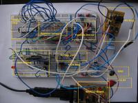
    And here is a small photo of how this system was built on a contact plate and everything started off. For those who fought the deal several times and gave up ;)
    Atmega Fusebit Doctor (HVPP + HVSP) - fix fusebits
    The author of the photo is a certain Russian, he has no influence on the quality of the photo.
  • #246 13261299
    Jogesh
    Level 28  
    Hello
    Thank you for the quick reply. I gave the inverter from the programmer willem, so I think it should work. I only have to check the voltage in the catalog note and choose the resistors. Then I start designing PCBs. However, I prefer this testing method, especially since it will be the next version of the doctor that I will do, so I already have some PCB done.

    best regards
    NS.
  • #247 13262090
    manekinen
    Level 29  
    My other device using HVPP, which has already been "created" since the beginning of 2013 and cannot be built, uses just such a converter based on MC34063, but as I suggested earlier, the whole converter is switched on with the P mosfet and there is only a pulldown and a capacitor behind it.

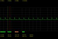
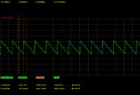
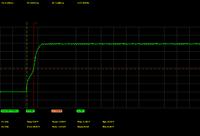
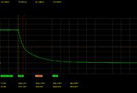
    The experiments took some time because I couldn't get the right output voltage. Pulldown had to be strong to cut the power off relatively quickly when the inverter stops, the capacitor would have to be large to smooth the peaks of the working choke. The whole problem is that the stronger the pulldown, the higher the oscillation at the output and you need to give a larger capacitor. The larger the capacitor, the longer the output voltage lasted after turning off, and a stronger pullup must be produced :)

    If I find a diagram somewhere (when I changed my laptop, I lost some of the documents), I will paste it, I only found oscillograms how the 12V line behaved:

    Unloaded output switched on
    Atmega Fusebit Doctor (HVPP + HVSP) - fix fusebits

    Loaded with 10mA (and still not enough)
    Atmega Fusebit Doctor (HVPP + HVSP) - fix fusebits

    Rising edge:
    Atmega Fusebit Doctor (HVPP + HVSP) - fix fusebits

    Falling slope:
    Atmega Fusebit Doctor (HVPP + HVSP) - fix fusebits

    And such a thing was acceptable by the initiated system, although there were sometimes problems. With the loaded output above 10mA, i.e. oscillations greater than 0.5VPP, eggs appeared.

    More about the choke. I think I gave 330uH, it is known that the greater the noise will return to the 5V power supply, and this significantly influenced the work of the whole, the more that it was powered from USB via the ISP programmer. So you also need to put a large capacitor in front of the MC circuit.

    The voltage setting resistors are 3K9 and 33K from what I see on the pcb, but both were selected individually, one was the smallest and the other the largest of the entire tape - then with 5V at the input I got a nice 12V.

    If you can do it better and simpler, it will be nice if you share your knowledge.

    And this is the prototype board of my magic device, it has been lying around since spring, I have to start finishing it, there is not much left, but as it is with prototypes, there are still some anomalies in operation ... the doctor had the same problems, but he was "on the people" :)
    Atmega Fusebit Doctor (HVPP + HVSP) - fix fusebits
  • ADVERTISEMENT
  • #248 13296958
    tomastom
    Level 12  
    Hello.
    I have a question for the author, is it possible to connect the display as in one of the photos or were they only the initial phases of the project and now it is no longer possible?

    And the second question is how to connect the pins from atmega2560, which are given in pdf "Parallel Programming"
    The pins that are described in the diagram of the "40-pin" socket PB0-PB7 and your device are described differently as it is for the atmega2560 and whether you still connect it in the same order as in figure PB0 to PB0 or according to the descriptions and then, for example, atmega2560 PB0 is SS and in the scheme t0 / XCK and the SS is on the PB4 pin.
    Or maybe you would have a diagram of such a connection somewhere in the test?
    best regards
  • #249 13297135
    manekinen
    Level 29  
    PB7-PB0 is DATA7-DATA0 respectively, the rest of the pins are known.
  • #250 13299741
    tomastom
    Level 12  
    OK, thank you, I managed to fix the prock, but I do not know if there is an error in the diagram, there is a 100-ohm resistor on the T3 transformer and after connecting it heats up terribly and until I fired it, the system did not want to work, unless I connected something wrong because I did it on plate for quick assembly.
    In any case, it worked without this resistor.
    best regards
  • #251 13346585
    manekinen
    Level 29  
    Hello, the final update for the system - 2.12 is being prepared.

    At the moment, the only planned changes are:
    -fixing incorrect reading of lockbits from the attiny12 system, and maybe problems with other systems, I have to review the reports
    - adding a time limit while waiting to enter the programming mode, at the moment when we start the system without the patient inserted, the system waits indefinitely with increased voltages of 5V and 12V. After adding the delay, the chip will return the message "no chip" after a short while, e.g. 1 second, as it should be done from the beginning.

    The update will only affect the program, not the board.

    As this will definitely be the last update, I am curious about your suggestions for changes, improvements and fixes. Here, on priv or email. There is not much free memory left in the processor (only 56 bytes for m8) but you can definitely figure something out.

    If someone has reported something to me in the subject or privately and it has not been corrected, please remind me, there is too much of it for me to review everything (on the project home page almost a thousand comments from around the world).
  • #252 13376594
    LOCODELAFONOLA
    Level 11  
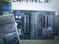
    ESPA?OL: hola mi nombre es juan y soy de argentina .tengo muchos atmega8515 y attiny2313 rotos por ser principiante y no saber he armado Atmega Fusebit Doctor y tengo tan solo (1) uno atmega8L-8pu y mi duda es como programo los fusebit uso el programa ponyprog y programador si-prog adjunto una imagen del ponyprog de fuces en blanco
    Atmega Fusebit Doctor (HVPP + HVSP) - fix fusebits

    POLACO: Hello my name is John and I am from Argentina. Thisgo many atmega8515 attiny2313 broken down to be a beginner and not knowing I can have an Atmega Fusebit Doctor and I only have one (1) atmega8L-8pu and my question is how to program the fusebit ponyprog program i si-prog programmer picture fuces ponyprog blank with already thank you for the reply ... John
  • #253 13438993
    seba_x
    Level 31  
    I need to revive the Atmega48V, the DATA lines are connected to the C and D port pins, can you write me which DATA lines to connect to which pins?
  • #254 13440732
    seba_x
    Level 31  
    Did I understand the pdf from atmegi48 correctly? :

    DATA0 - PC1
    DATA1 - PC0
    DATA2 - PB5
    DATA3 - PB4
    DATA4 - PB3
    DATA5 - PB2
    DATA6 - PB1
    DATA7 - PB0
  • #255 13447494
    LOCODELAFONOLA
    Level 11  
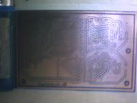
    CASTELLANO: hola amigos .. les cuento que llevo (4) atmega8 bloqueados sin exito al grabar atmega8 doctor alguien que me explique la forma corecta de hacerlo con ponyprog dispongo de atmega8-16pu nuevo aca adjunto imagenes de mis placas espero que les guste y gracias de mis placas espero que les guste y gracias al author juan POLACO: Hello friends ... Tell them that (4) atmega8 blocked without success to record atmega8 doctor someone explain to me the correct way to do it with ponyprog atmega8-16pu new deputy here you have photos from my album I hope you like and thanks this author John Atmega Fusebit Doctor (HVPP + HVSP) - fix fusebits Atmega Fusebit Doctor (HVPP + HVSP) - fix fusebits
  • #256 13448054
    seba_x
    Level 31  
    Ok, I have already found the pin description in the picture:

    Atmega Fusebit Doctor (HVPP + HVSP) - fix fusebits
  • #257 13450471
    manekinen
    Level 29  
    seba_x wystarczyło zajrzeć do schematu, wszystkie piny są tam opisane - przy każdej podstawce.

    LOCODELAFONOLA your automatic polish translation is useles, can't understand what is the problem. If you want to get help, please write in english (not automatic translated, it will be useless too).
  • #258 13467235
    LOCODELAFONOLA
    Level 11  
    thank you very much friend manekinen., I have checked pcb., it is correct., there are no short circuits and cut not tracks., record with ponyprog and serial engraver SI-PROG., I have 5v and 12v reset in a few seconds., led green strober in a few seconds., then led red always .. vercion of PCB and firmware update11., 12v extracted of computer., and fusebit atmega 8-16pu as the image., repairer does not work fusebit., I tried with virgin avr atmega8515-16pu and atmega8-16pu. led red ignition also Atmega Fusebit Doctor (HVPP + HVSP) - fix fusebits
  • #259 13589256
    yogi009
    Level 43  
    Hello,

    I just got the need to do such a doctor for AVR. I am playing with the board in Eagle a bit and I am wondering about a few details already in the schematic (package in version 2.11).

    1. in the stabilizer section, C2 and C3 are not connected with each other with positive ends, which is suggested by the 780x catalog note, and there are also two power markings: Vcc and + 5V. I should treat it as an error and connect the line between these capacitors?

    2. at the T3 collector, the + 12V mark appears, which is nowhere else in the diagram. Should I treat them the same as V +? Are they the same potentials?

    3. I understand that it would be optimal to stabilize + 12V (7812) and + 5V (7805), then there is no possibility of overheating with the input voltage? As I guess, L series stabilizers with 100mA efficiency are enough?

    Best regards and congratulations on an interesting project.
  • #260 13589581
    karel21
    Level 28  
    At home, I gave 7812.7805 stacked, one on top of the other, lying down.
  • #261 13589616
    yogi009
    Level 43  
    Can you, buddy, explain the first two points to me? I'm sitting on the Eagle and trying to do it in SMD (what I can do, of course), but inaccuracies in the diagram stopped my work.
  • #262 13589977
    Gienek
    Level 37  
    I do not know what scheme you are using, that you have C2 and C3 that do not have positive ends connected (they should be connected.
    This + 12V voltage is used for additional "adapters" (it is led out to the X4.
    In fact, I am unnecessarily responsible for the Author. Go to its website and there is a version for SMD in the files section. (http://mdiy.pl/atmega-fusebit-doctor-hvpp/)
  • #263 13590049
    karel21
    Level 28  
    We are indeed responsible for the author of the project, but the V + is powered by an external 12V power supply.
    Vcc power goes to switch S1, it is in the schematic.
    Now, as for the stabilizers, the 7805 can be in the L version, while the 12V should be more efficient. For me, when powered from the 15V power supply, when the system is turned on, it consumes 158mA (jerk), 41mA in standby, maximum 210mA during "work".
  • #264 13590564
    yogi009
    Level 43  
    It is a pity, I have such a nice stabilizer from Toshiba 12V 150ma In TO-92 housing, but I can see that it is not enough.

    Colleague Gienek , diagram from the author's website, package version 2.1, there is no this connection in the diagram, and the double descriptions (different) are a bit misleading. The positive voltage signal could be called anywhere, e.g. V +, after a possible 78M12 stabilizer, e.g. + 12V, and after a 78L05 stabilizer, e.g. + 5V. And then, when creating your own PCB, you don't have so many basic questions :-)

    The SMD version on the author's website is version 1.0, from what I understand it has bugs. Of course, visually (to suspect topology) it is useful, but I sense something that you will need to make a new SMD board based on diagram 2.1. I do not know yet whether I want to change everything possible to SMD, maybe I will leave the controllers in THT, but I will move the small parts to small housings.
  • #265 13590783
    Gienek
    Level 37  
    Well, with such experience, and you don't carefully analyze the scheme.
    This V + it is the voltage supplied from the external power supply, while the voltage marked as + 12V, it is the voltage supplied to the "doctor" at the right moment (controlled by the processor), therefore this version is unacceptable:
    Quote:
    The positive voltage signal could be called anywhere, e.g. V +, after a possible 78M12 stabilizer, e.g. + 12V,


    If I were you, I would do this: he used the Eagle 2.1 scheme, introduced the appropriate corrections and changed (what was possible) the SMD component housings and then he made "his" PCB.

    Thank you for "provit", but it was enough to "helped".
  • #266 13591891
    yogi009
    Level 43  
    Buddy, there is no button here [He helped] :-)
  • #267 13592793
    manekinen
    Level 29  
    I don't have a look at the diagram now, so I don't remember the markings, but these power rails must not be connected. They have different names because they are quite different signals in eagle. It will be best if you open the schematic itself in ver. 2H, you will replace the component housings with smd, and then create a pcb. Don't touch anything else. Replace this row of 1K resistors with 330 or 470 ohms. Such things are explained in the description, probably all doubts are dispelled in the FAQ section (on the project website), so be sure to read. This smd version from the website is not my authorship and I cannot vouch for it, apparently it's ok, it's only in an older version and will not work with the new batch. Overall, some lopsided pcb, I'm sure you will come out better :-) 78L05 is enough, in case the voltage drops you can give a slightly weaker pull resistor after the 5v transistor.

    And if someone is responsible for me in the subject, I will certainly not be offended and I will thank you sooner because I do not have time or opportunity to write back. Also, if someone knows the answer to the questions asked in the topic, go ahead :-) And those sent to me privately, unfortunately, very often remain unanswered, for which I apologize and encourage you to write in public.

    Best regards.
  • #268 13593707
    aniołek
    Level 12  
    Add a modification of the original project - I have a dry-painted version using the Arduino mini board + shields. The Arduino itself has also been slightly repainted (quartz removed), and the shield has all signal outputs in the form of a ribbon. If this is the will of the people - I will dig the lapik and post it, but I make a reservation - these are only paintings not yet tested in action !!

    As for the smd version placed on the Author's website - it was made in the SprintLayuot program, which, compared to Eagle, is at the level of Paint to some Cad. I have been using this program myself for several years (originally in version 4, now - 5), and its biggest problem is the lack of linking the scheme with the project, although the latest version 6 is supposed to do it. It has another nice function - you can take a photo or an original tile as a background, and paint your paths on it. ..
  • ADVERTISEMENT
  • #269 13632380
    pawel26021995
    Level 12  
    Hello, I tried to unlock 4 ATMEGI with Atmega Fusebit Doctor and unfortunately it failed, it is impossible to save new settings. Can anything else be done with them ?? Any advice?

    code from the terminal:
    1 atmega8a-pu
    
    Welcome                                                                         
    AVR Atmega fusebit doctor (HVPP+HVSP) version 2.11                              
    http://diy.elektroda.eu/atmega-fusebit-doctor-hvpp                              
    Usage in commercial/profit purposes not allowed                                 
                                                                                    
    MANUAL HVPP MODE                                                                
                                                                                    
    Init programming...  DONE                                                       
    Read signature...    1E 93 07                                                   
    Searching chip...    no names in 8kB ver                                        
    Read fusebits...     L:E1 H:E1 E:00                                             
    Should be...         L:E1 H:D9 E:00                                             
    Lockbits...          DISABLED (FF)                                              
                                                                                    
    What to do?...                                                                  
    1 - write fusebits                                                              
    2 - modify fusebits                                                             
    3 - set lockbits                                                                
    4 - chip erase                                                                  
    5 - end                                                                         
                                                                                    
    Chip erase...        DONE                                                       
                                                                                    
    What to do?...                                                                  
    1 - write fusebits                                                              
    2 - modify fusebits                                                             
    3 - set lockbits                                                                
    4 - chip erase                                                                  
    5 - end                                                                         
                                                                                    
    Writing E1 D9 00...  DONE                                                       
    Verifying...         L:E1 H:E1 E:00- FAIL!                                      
    Please try again...                                                             
                                                                                    
    What to do?...                                                                  
    1 - write fusebits                                                              
    2 - modify fusebits                                                             
    3 - set lockbits                                                                
    4 - chip erase                                                                  
    5 - end 
    
    
    2 atmega328p-pu
                                                                                    
    Welcome                                                                         
    AVR Atmega fusebit doctor (HVPP+HVSP) version 2.11                              
    http://diy.elektroda.eu/atmega-fusebit-doctor-hvpp                              
    Usage in commercial/profit purposes not allowed                                 
                                                                                    
    MANUAL HVPP MODE                                                                
                                                                                    
    Init programming...  DONE                                                       
    Read signature...    1E 95 0F                                                   
    Searching chip...    no names in 8kB ver                                        
    Read fusebits...     L:C4 H:D9 E:FF                                             
    Should be...         L:62 H:D9 E:FF                                             
    Lockbits...          DISABLED (FF)                                              
                                                                                    
    What to do?...                                                                  
    1 - write fusebits                                                              
    2 - modify fusebits                                                             
    3 - set lockbits                                                                
    4 - chip erase                                                                  
    5 - end                                                                         
                                                                                    
    Chip erase...        DONE                                                       
                                                                                    
    What to do?...                                                                  
    1 - write fusebits                                                              
    2 - modify fusebits                                                             
    3 - set lockbits                                                                
    4 - chip erase                                                                  
    5 - end                                                                         
                                                                                    
    Writing 62 D9 FF...  DONE                                                       
    Verifying...         L:C4 H:62 E:FA- FAIL!                                      
    Please try again...                                                             
                                                                                    
    What to do?...                                                                  
    1 - write fusebits                                                              
    2 - modify fusebits                                                             
    3 - set lockbits                                                                
    4 - chip erase                                                                  
    5 - end   
    
    3 atmega8a-pu
    
    Welcome                                                                         
    AVR Atmega fusebit doctor (HVPP+HVSP) version 2.11                              
    http://diy.elektroda.eu/atmega-fusebit-doctor-hvpp                              
    Usage in commercial/profit purposes not allowed                                 
                                                                                    
    MANUAL HVPP MODE                                                                
                                                                                    
    Init programming...  DONE                                                       
    Read signature...    00 01 02 - FAIL!                                           
    Trying T2313 pinout..00 01 02 - FAIL!                                           
    Type the signature:  1E   
    
    
    4 atmega8a-pu
    Welcome                                                                         
    AVR Atmega fusebit doctor (HVPP+HVSP) version 2.11                              
    http://diy.elektroda.eu/atmega-fusebit-doctor-hvpp                              
    Usage in commercial/profit purposes not allowed                                 
                                                                                    
    MANUAL HVPP MODE                                                                
                                                                                    
    Init programming...  DONE                                                       
    Read signature...    FF FF FF - FAIL!                                           
    Trying T2313 pinout..FF FF FF - FAIL!                                           
    Type the signature:  1E     
    
  • #270 13632406
    manekinen
    Level 29  
    Have you checked the correct operation of the system on a working prock?

Topic summary

The discussion revolves around the Atmega Fusebit Doctor, a device designed to repair misconfigured fuse bits in AVR microcontrollers, particularly the Atmega series. Users share their experiences with the device, detailing issues such as incorrect fuse settings, inability to read signatures, and challenges in programming various Atmega models. Solutions include using the device to reset fuse bits, ensuring proper connections, and troubleshooting with UART communication. The conversation highlights the importance of correct voltage levels, resistor values, and the need for careful assembly to avoid short circuits. Users also discuss the potential for using the device with different AVR models and the necessity of firmware updates for compatibility.
Summary generated by the language model.
ADVERTISEMENT