logo elektroda
logo elektroda
X
logo elektroda
ADVERTISEMENT
Treść została przetłumaczona polish » english Zobacz oryginalną wersję tematu
  • #31 15549825
    morph13
    Level 25  
    maciek95k wrote:
    ........ I am also interested in how the rotation mechanism is built in such robots. ............ Has anyone had contact with such robots here and could someone tell me something?

    Hello friend
    First, congratulations on making an amateur 5-axis robot arm for purely experimental purposes. Why not a "welding robot", here I agree with some of the arguments of one of the speakers who discussed welding in his post and I will not repeat it.

    But to the point.
    As help and knowledge enrichment. It has a Polish translation (only book, not pdf) of the ABB instructions for the IRB1400 and IRB6400 robot. And if possible, I can send you descriptions that interest you in the form of a scan or photo (provided that it does not infringe ABB's copyrights), starting from technical issues related to the construction (including construction details of individual axes), through control methods and ending with a diagram .

    However, I will quickly suggest that the reduction gears of individual axes are now practically only cycloidal (in new designs), once planetary. The driving motors are only 3F servos + resolver + electromagnetic brake.
    Control based on two computers, one for controlling the axis inverters and communicating with the measuring board called SMB (all resolvers are connected to it) and performing calculations related to the trajectory and a second computer that handles the rest, i.e. communication with the teach pendant, language interpreter RAPID, editing and maintenance of user software, etc. I have intentionally omitted the description of power circuits, security, data recording, I / O card handling. And there is a lot of it.

    If you have programming skills and you intend to continue to develop your design, I would suggest that you follow the path that ABB robot developers have taken with regard to amateur possibilities. So, on a PC, you edit individual points of the robot's movement, initial calculations of the position, all this is sent to an additional module, e.g. in the form of a Raspberry Pi via the Eth link, and it supports everything related to motor management (whether it is servos or steppers), encoders and monitoring the calculated trajectory of the individual axes. And all this "embellished with mutual synchronization of all axes" with complex motion in some predetermined unit of time.

    An important issue, apart from motor skills and kinematics of the arm, is also the choice of the coordinate system in which the robot is to work. For professional solutions, these are at least three (global, basic, from the point of view of the TCP attachment, from the point of view of the tool tip, etc.). For amateur constructions, I would choose the TCP point (for a 6-axis robot it is the center of the tool mounting disk on the rotary axis No. 6) and I would add a software correction for the length of the "torch pipe". For the coordinate system, I would choose the primary XYZ. The basic type of movement is only linear, and after the joint is under control, then circular.

    I apologize if I have covered a lot of topics at once and did not describe them in detail, or even did not cover them at all.
    Do you have any specific questions, ask (ABB robots only), I will answer based on my knowledge or using the documentation as I have free time.

    Maybe this thread will develop something like "amateur roboto construction for everyone".
  • ADVERTISEMENT
  • #32 15550097
    cooltygrysek
    Conditionally unlocked
    Morph13 This is an open admission to disclosing ABB's copyrights. :-) If someone has published a book, it will not infringe the copyright, because the commercial production will not be conducted by a colleague, but it can be different. Please write such things in private. As for the transmission, you are right, but not entirely correct. The transmission depends on the assumed speed of the arm movement and the weight of the lifting capacity. An electromagnetic brake is no longer used, except for absolute lock, but dynamic. water-cooled or, more frequently, glycol-cooled engines. But it also depends on the power, number of cycles per hour, speed, precision of movement and repeatability as well as own and transferred weight, etc. I have contact with both robots and high-power automation Asea Brown Boveri, Hitachi, Honda, etc. River theme.
  • ADVERTISEMENT
  • #33 15550236
    morph13
    Level 25  
    cooltygrysek wrote:
    Morph13 This is an open admission to disclosing ABB's copyrights. :-) If someone has published a book, it will not infringe the copyright, because the commercial production will not be conducted by a colleague, but it can be different. ....

    Prophylactically, I found it better to bring up this topic. As for the materials, of course only on PV.

    cooltygrysek wrote:
    ....... As for the transmission, you are right, but not quite right. The transmission depends on the assumed speed of the arm movement and the weight of the lifting capacity. ......

    I strongly support, which is why at the end I stated that I treated many things superficially or did not even mention them

    cooltygrysek wrote:
    ..... An electromagnetic brake is no longer used, except for absolute locking, but dynamic. water-cooled or, more frequently, glycol-cooled engines. But it also depends on the power, number of cycles per hour, speed, precision of movement and repeatability as well as own and transferred weight etc etc .....

    IRB1400, 6400 and several other electromagnetics as a parking brake, braking with the so-called engine, as older and more experienced specialists say, I would use a different term. As for cooling with water and glycol in small robots (rather welding), I have not met, but I would be happy to see materials or photos related to this topic

    cooltygrysek wrote:
    .... I have contact with both robots and high-power automation Asea Brown Boveri, Hitachi, Honda, etc. River theme.

    The river is correct, but if so, PC + Rasp Pi, a few steppers with a position transducer (encoder, resolver), reducers, and of course a well-thought-out simple arm structure (something from KUKI, ABB, MOTMANA, etc. as in the topic), it could take shape ..... maybe not without pain and financial outlay, but ... something would certainly come out of it.
  • #34 15550410
    cooltygrysek
    Conditionally unlocked
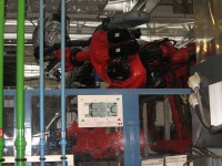
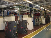
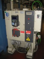
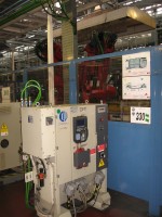
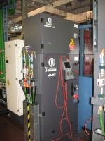
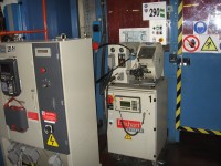
    Hehe, you have some pics from Fiat Auto Poland Tychy, I am enclosing an attachment with photos of robots, mainly Comau, but there are also hitachi and small ABB. All cooled with glycol. The exchangers are in the supply and cooling control stations. Each station has a so-called Pendant. Each is connected to the main cooling tower.
    In the last photo you have a 400 kg drum welding wire feeder.
  • ADVERTISEMENT
  • #35 15684665
    Soldier_Bk
    Level 10  
    Hello.
    Recently I was playing with Mitsubishi robots, a so-so 5-axis arm with a gripper for the production line programmed in melfa-basic.
    If you want to program the robot EXACTLY, a teaching panel with a jog function is necessary here.
    There, the positions are programmed like this:
    1. Set the position along the axes, e.g. for the robot to catch something
    2. We create a field in the position table
    3. We assign there a previously set position
    4. Enter the name of the item in the program.

    As for the construction, everything is based on car servos powered by DC, usually 200v, and somehow I don't see any problems with pulling, and the pneumatics are there only for the gripper.

    I can tell you something more about these designs if they are interested.

    Edit: Btw:
    cooltygrysek wrote:
    Hehe, you have some pics from Fiat Auto Poland Tychy, I am enclosing an attachment with photos of robots, mainly Comau, but there are also hitachi and small ABB. All cooled with glycol. The exchangers are in the supply and cooling control stations. Each station has a so-called Pendant. Each is connected to the main cooling tower.
    In the last photo you have a 400 kg barrel for welding wire


    Nice trip :) envy :D
  • ADVERTISEMENT
  • #36 15686517
    cooltygrysek
    Conditionally unlocked
    I am in Fiat from time to time when UR does not cope with crap on robots or with Siemens automation. With the self-learning mode, let's not exaggerate with accuracy, because usually the robot from the zero state after auto-calibration works according to the program assumption in the process of designing the body points, eg. The self-learning mode is good so that in certain situations it is possible to correct or add some movement beyond the program.
  • #37 16843007
    eboy
    Level 2  
    Hello

    The topic has dried up - and I am not surprised because it is very difficult. For my part, I would like to add that without cooperation with the camera and correcting the robot's movements on the basis of the image, it will not be possible. An example like this is enough. Welding a cube made of sheet metal, e.g. 3mm thick. It's simple in the coach and in theory, but in reality .... It is enough to mention that the sheets of metal purchased in the warehouse are not cut at right angles. They have a bug. About 0.5 cm per meter of length. When welding a 0.5x0.5x0.5m container, the vertices diagonally have an error of around 2cm (in relation to the ideal cube design written in the program). And it is already after welding, because in this case you can afford an error of 1-2mm.
  • #38 21188062
    olatundeprestige
    Level 1  
    I need help or rather a consultant to assist me in building a CNC welding machine

    Added after 49 [seconds]:

    I need help or rather a consultant to assist me in building a CNC welding machine

Topic summary

The discussion revolves around a DIY CNC welding robot project, initially built by a technical school student. The robot, which is still under development, was designed for exhibitions rather than practical welding applications. Participants express admiration for the design while raising concerns about the robot's wiring safety during welding and the quality of welds produced. Suggestions include using plasma cutting capabilities, improving control systems, and considering alternative motor types like wiper motors or stepper motors for better accuracy. The conversation also touches on the importance of proper welding techniques, the need for a more robust control system, and the potential integration of sensors and encoders for enhanced functionality. Participants share insights on professional robots, including brands like ABB and KUKA, and discuss the complexities of welding automation.
Summary generated by the language model.
ADVERTISEMENT