logo elektroda
logo elektroda
X
logo elektroda

Printing with a laser printer on a PCB laminate

lukasku 58635 111
ADVERTISEMENT
Treść została przetłumaczona polish » english Zobacz oryginalną wersję tematu
  • #31 16632249
    krisRaba
    Level 31  
    lukasku wrote:
    how to "pull" smd pads with Top without paths?
    < br />
    I do not think you need to take paths from the layer. The SMD pads themselves are on the layers for the soldering paste, in gerbers probably the * .gtp for the TOP and * .gbp layers for BOTTOM.
  • ADVERTISEMENT
  • #32 16632314
    lukasku
    Level 10  
    I've found in * gts, thanks a lot. Unless there is a different way?
  • ADVERTISEMENT
  • #33 16632601
    krisRaba
    Level 31  
    * .gts is from soldermask, so there will be not only SMD pads, but also unmasked grommets and leaded pads ...

    Although returning to the fact that you want to do a soldermask ;) , this is all the information you need, so you do not have to get them out of other sources ;) I have instructed * .gtp / *. gbp if you really only needed SMD, as you wrote - there are no vias and threaded pads on them.
  • #34 16632662
    lukasku
    Level 10  
    krisRaba wrote:
    * .gts is soldermask so there will be not only SMD pads, but also unmasked grommets and leaded pads ...

    Although returning to the fact that you want to do a soldermask ;) , this is all the information you need, so you do not have to get them out of other sources ;) I have recommended * .gtp / *. gbp if you really only need SMD, as you wrote - there are no through holes and pads on them.

    I understand a little confused, because I thought that it can be done in some way using layers without the generation of Gerbera files (for example, change some miracle layer, among others, T / B Cream so pads were not "checked" and full). But everything is clear and thanks again.
  • #35 16638999
    RomanFilipecki
    Level 18  
    The tile looks beautiful, almost unbelievably beautiful. I am also wondering about the drilling method, probably not by hand?
  • #36 16639443
    lukasku
    Level 10  
    RomanFilipecki wrote:
    The tile looks beautiful, almost unbelievably beautiful. I am also wondering about the drilling method, probably not by hand?

    Unfortunately, for now, by hand. I have not yet made a simple drill bit to make holes, although I have an idea in my head.
  • #37 16640045
    Anonymous
    Level 1  
  • #38 16640112
    Freddy
    Level 43  
    Kraniec_Internetów wrote:
    And maybe go further and laser-evaporate copper?
    Sure, only 2W is not enough, you need 100W at least. :)
  • #39 16640122
    Anonymous
    Level 1  
  • #40 16640237
    RomanFilipecki
    Level 18  
    While I am inclined to believe in making PCB of this quality in amateur conditions, I do not believe in manual drilling with such accuracy. Look even the viages (with a smaller cake diameter) are drilled perfectly, centrally and the lack of craters after the drill. It's totally unbelievable for me ...
  • ADVERTISEMENT
  • #41 16640415
    wada

    VIP Meritorious for electroda.pl
    Kraniec_Internetów wrote:
    Freddy wrote:
    Sure, only 2W is a lot of it little, you have to do it with 100W at least.

    And some program that will disappear only copper, and do not dig this laser into the earth's core. :)
    https://www.youtube.com/watch?v=TMCjWslnM1A

    More so


  • #42 16640475
    lukasku
    Level 10  
    RomanFilipecki wrote:
    While I am inclined to believe in PCB quality in amateur conditions, I do not believe in manual drilling with such accuracy. Look even the viages (with a smaller cake diameter) are drilled perfectly, centrally and the lack of craters after the drill. Quite unbelievable for me ...

    But the pictures do not have a plate with holes :) there are only 4 positioning two-sided prints :D I honestly do not know what's going on ;)

    By the way, I will ask you whether the eco-solvent ink is suitable as a "soldermask"? I think so, because I have a converted Epson for PCB printing and if it were suitable ...
  • #43 16640630
    Anonymous
    Level 1  
  • #44 16640838
    wada

    VIP Meritorious for electroda.pl
    Kraniec_Internetów wrote:

    But this is a factory solution, probably cosmically expensive. That was created in someone's garage. Nevertheless, what you sent drilled holes :O

    And copper is a very nasty material for the laser, not only does it act like a mirror and more than 50% of the light reflects and you have to treat it at a slight angle so that the reflection does not hit the lens again, it is also a very good conductor of heat, and needs almost three times more energy than stainless steel.
    How powerful it must be to blow and draw the air to draw the evaporated copper and not to burn the laminate.
    I will have to see at work how our lasers will treat laminated tiles.

    lukasku wrote:

    By the way, I will ask you whether the eco-solvent ink is suitable as a "soldermask"? I think so, because I have a converted Epson PCB, and if it would be suitable ...

    Forget - you would have to put a lot of layers on
    What is different? Solvent but UV cured
  • #45 16640846
    Anonymous
    Level 1  
  • #46 16640942
    lukasku
    Level 10  
    wada wrote:

    lukasku wrote:

    By the way, I will ask you whether the eco-solvent ink is suitable as a "soldermask"? I think so, because I have a converted Epson PCB, and if it would be suitable ...

    Forget - you would have to put a lot of layers on
    It's different Solwentowy ale hardened UV


    I found something like that (under the micro piezo). Due to the fact that I do not know much about these matters, I would like to ask if UV and solvent alone are enough to be sure about its usefulness, or maybe some test etc. ? If so, then I would try it and describe it here.
  • ADVERTISEMENT
  • #47 16640991
    RomanFilipecki
    Level 18  
    Sorry, I was absolutely convinced that she is drilled perfectly with the perfect drill with incredible precision. Well now a challenge in front of you.
  • #49 16656061
    pier
    Level 24  
    lukasku wrote:

    The scheme looked like this, cleaning the plate with water paper, degreasing with acetone, the position of a thin layer of silicone and spreading with a cloth / breakfast paper until the plate looks like dry, after transferring the print to the plate basking 180-190 degrees 2-3min

    I tried to use silicone. The effect is that chalk is easier to leave the laminate and maybe the quality is slightly improved.
  • #50 16676668
    lukasku
    Level 10  
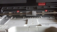
    Hello, I decided to test the first modernization of this Lord, namely the Lexmark E260. Due to the fact that most wrote that the whole line is similar and I could not find E260 I bought E460 and here a small zonk. Mechanically, you can say 90% the same but 460-a is faster and otherwise gets paper. This information is for those interested in converting these printers. What is related to this, the charge to attiny will also not "fit". I wrote my batch but ATTINY 2313a to have diodes (controls) because I did not know the time of passing through the sensors (I have an oscilloscope, but so far I did not buy a second probe, which would ease the matter of paper passing through the sensors). My program starts when the clutch is engaged, which slides the paper into the printer. The rest is similar to this: http://www.instructables.com/id/Modification-of-the-Lexmark-E260-Laser-Printer-for/. As a further test for lack of time I will be doing in about a month, but I have a few insights. Well, this printer in comparison to Pantum in modification at first glance seems more complicated, but as it happens later when you understand its operation is really simple. In addition, it is made much more solidly. Personally, I liked it and has the advantage that outclasses all other printers (especially for such reworkings and possible mistakes), namely a photoconductor drum costs PLN 15 and all toner with a drum about 50. In comparison with Pantum (where it is easier to rework ), where the toner drum costs about 180 PLN is a big difference :) ] [movie: ec27fb7f07] https://filmy.elektroda.pl/ 71_1504342816.mp4 [/ film: ec27fb7f07]
    ] Link [/url]
  • #51 16676933
    jacynka84
    Level 26  
    Can not do without this attiny? Can not you just stick to the A4 sheet of this laminate? Then generate PDF and there you can position where it is supposed to be on the page, you can also manipulate in free inkscape. Millimeters agree one day I printed more than once and everything was correctly dimensioned but you have to tick in print pdf as 100% scale.
  • #52 16677056
    lukasku
    Level 10  
    jacynka84 wrote:
    Can not do without this attiny? Can not you just stick to the A4 sheet of this laminate?

    Mechanically it is not easy, because the card is pulled up (folded) by the tray
    Printing with a laser printer on a PCB laminate
    When it comes to some kind of shallow conversion, there is not much space and I even tried to convert it simply by adding a resistor to the fixer. Unfortunately, this feeder is small and does not really want to draw a CD. Ultimately, in "my" processing will be an electromagnet (with the recovery of this printer) introduced (pushed) automatically a disc which should give at least theoretically, for example, greater precision (but also convenience) with double-sided discs.
    In addition, the difference in what I do and the modification of M. Lerman is that in addition to the tray, for small tiles I can print the full A4, I personally wanted.
  • #53 16677092
    jacynka84
    Level 26  
    After all, if it is bent like a laminate, it will not be able to bend. The more so as the laminate will be able to go through the printer is the more ordinary card.
  • #54 16677121
    lukasku
    Level 10  
    jacynka84 wrote:
    After all, how bent like a laminate will not be able to bend. The more the laminate will be able to go through the printer, the more the card will be used.

    I do not think Attiny "emulates and synchronizes" only the printer's sensors and the tiles passing through it. With dimensioning I have no problem, because only the medium changes instead of the card, either directly laminate A4 or tray and on it the laminate for smaller prints. On the tray, you can also print a division etc.
  • #55 16677283
    jacynka84
    Level 26  
    Well ok, I understand.
  • #56 16736884
    Piotr160292
    Level 38  
    How do you do it that tiles go out so perfectly? oO I cut it all the time, or make some paths ... If you saw a plate from my power supply, you would catch your head ... I got pissed off like a fool, it did not work, and it turned out that it was just B327 he strolled me and denied me the path, I did not pay any attention and I had to give a piece because I did not want to do the other, knowing that it is most likely a waste of paper and toner, because the effect will be a little better ... I had the same relay to the state of my WS502. At that time I still had a jam and probably made 10 attempts, and for every 10 either the copper was podtrawiało or completely consumed. In the end I gave up and assuming that it is supposed to work primarily, do not look like, I chose the best of all of them and on such a stubby piece I put together ...
  • #57 16739639
    lukasku
    Level 10  
    Piotr160292 wrote:
    How do you do it that tiles look so perfect?


    But you also print? Is thermo transfer? Beginning next week, I will have more loosely this will show the printouts from the second printer. greetings
  • #58 16739792
    Piotr160292
    Level 38  
    No, I'm putting on the iron ... I just did not mention that I'm talking about thermal transfer. With the rest one and the other way the tiles came out like from the factory ...
  • #59 16740784
    lukasku
    Level 10  
    Piotr160292 wrote:
    No, I'm putting on the iron ... I just did not mention that I'm talking about thermal transfer. With the rest one and the other way the tiles came out like from the factory ...

    If your thermo transfer technique has a problem only with sub-treatments (I personally do not have the patience for thermal transfer :) ) I would try to heat the toner already transferred to the plate, or an ordinary hot air gun, or, in my case, in the oven for about 3 minutes ~ 180-200 degrees. Interestingly, the melting temperature of the toner is assumed to be ~ 180 degrees, I noticed that some toners get slightly sticky at much lower temperatures.
  • #60 16740791
    Piottr242
    Level 23  
    It may be a question of paper and temperature and the type of toner.
    Me, the thermal transfer went out the first time, printing with an old HP1010 printer on chalk paper specially bought for this purpose.

    Sometimes it happens that some path will not bounce and will stay on paper (but then it can be seen immediately), and this happens either in the case when some paproch comes under the paper, or uneven ironing, or uneven edge of the tile.
    The fact is that so far I have been ironing tiles not exceeding the surface of the tram ticket, I do not know if I can manage so much with a larger area.

Topic summary

The discussion revolves around the challenges and techniques of printing directly on PCB laminates using modified laser printers, particularly the Pantum and Lexmark models. Users share experiences with various methods, including the use of silicone spray to enhance toner adhesion and the hybrid approach of combining inkjet printing with toner transfer. Key issues include the need for precise laminate preparation, the durability of the toner, and the potential wear on printer components. Participants also explore the feasibility of using UV inkjet printers and CNC milling for PCB fabrication, highlighting the importance of print quality and the impact of different toners and papers on the final results.
Summary generated by the language model.
ADVERTISEMENT