FAQ
TL;DR: Pantum P2500 drum replacements cost PLN 180 (~€40) [Elektroda, lukasku, post #16774910]; “after 30 prints durability looks good” [Elektroda, lukasku, post #16628484] Use silicone spray, 0.8–1 mm registration holes, and correct sensor timing to get sub-10 mil tracks quickly.
Why it matters: Direct-laser printing slashes one-off PCB build time from hours to minutes without messy irons.
Quick Facts
• Typical track width achievable: 7–10 mil (0.18–0.25 mm) [Elektroda, lukasku, post #16970352]
• Replacement OPC drum costs: Pantum P2500 ≈ PLN 180; Lexmark E460 ≈ PLN 15 [Elektroda, lukasku, post #16774910]
• Silicone spray brand tested: K2 Perfect SIL, thin wiped layer [Elektroda, lukasku, post #16630866]
• Tray registration hole: 0.8–1 mm, ≤10 mm below NPIS sensor [Elektroda, silelis, post #16876682]
• Heating for toner hardening: 180 °C for 3 min or acetone vapour 30 s [Elektroda, lukasku, post #16740784]
Which laser printers are most often converted for PCB printing?
Pantum P2500/2502 and Lexmark E260/E460 dominate because their paper paths are almost straight and firmware is simple to spoof with an ATtiny13/2313 [Elektroda, lukasku, post #16774910] Samsung ML-1610 mechanics are similar but need extra feeder work [Elektroda, bodzio667, post #16793621]
What hardware changes are essential on a Pantum P2500/2502?
- Remove fuser and one roller.
- Add flat tray with insulation-tape drum guard.
- Fit slotted opto sensor plus ATtiny to emulate MFPS, PIS, ES timings [Elektroda, lukasku, post #16630102]
- Drill 0.8 mm hole in carrier for NPIS trigger [Elektroda, lukasku, post #16873331]
How do I stop the photoconductor drum from scratching?
Cover leading copper edge with ordinary PVC insulation tape; it “protects the drum against scratches” during 30+ prints [Elektroda, lukasku, post #16628484] Smooth laminate edges with 400-grit before feeding to avoid gouges [Elektroda, lukasku, post #16630866]
Why use silicone spray on the laminate?
A wiped-dry film of silicone increases toner adhesion and lets it survive acetone scrubbing; “toner placed perfectly and is hard to wash off with acetone” [Elektroda, lukasku, post #16629802] It also helps paper release during thermo-transfer trials [Elektroda, marianm68, post #16782304]
What is the correct registration-hole position for Lexmark E260?
Drill a 0.8–1 mm hole about 7–10 mm downstream of the NPIS sensor and 2–5 mm from the sheet edge; farther holes miss the 500–550 ms timing window and toner never fires [Elektroda, silelis, post #16876682]
How fine can tracks and gaps be with this technique?
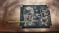
Users report reliable 8 mil tracks; one achieved 7 mil between pads on 195 × 255 mm boards [Elektroda, lukasku, post #16970352] Very large copper pours may under-etch if toner coverage is thin [Elektroda, ksik, post #16795680]
Best way to strip toner after etching?
Label-off citrus aerosol dissolves stubborn toner quickly [Elektroda, silelis, post #16778224] For standard toner, xylene or acetone suffice; however certain refill batches resist even nitro solvent [Elektroda, lukasku, post #16777944]
How accurate is double-sided alignment?
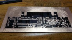
Using dual optical holes and the electromagnet tray, Lexmark E460 achieved <0.5 mm front-to-back offset on a 19 × 19 cm board [Elektroda, lukasku, post #16872749] Edge-case: missing one hole forces multiple re-prints and drum wear [Elektroda, silelis, post #16875143]
Could eco-solvent or UV ink serve as solder-mask?
Eco-solvent alone is too thin; you’d “have to put a lot of layers” and adhesion is weak [Elektroda, wada, post #16640838] UV-curable ink formulated for piezo heads is promising but needs tests for heat and chemical resistance [Elektroda, lukasku, post #16640942]
What common failures should I expect?
- Timing mis-match: printer feeds but no image.
- Drum scratched by un-deburred laminate.
- Refill toner with higher melt point leaves voids over 10 mil copper areas [Elektroda, ksik, post #16795680] “I killed the drum” after mis-aligned hole, warns one user [Elektroda, silelis, post #16968934]
How do I run the direct-laser printing cycle?
- Clean, lightly sand, degrease copper; wipe on thin silicone film.
- Feed laminate through modified printer; ensure 180 °C fuser is disabled.
- Bake board at 180 °C for 3 min or expose to acetone vapour 30 s to harden toner [Elektroda, lukasku, post #16740784]
Is CNC milling or UV-laser a better option?
CNC avoids drum wear and yields drilled vias, but costs more and struggles with <8 mil gaps [Elektroda, silelis, post #18276685] UV-laser ablation of black paint needs >100 W for copper removal, far beyond hobby budgets [Elektroda, Freddy, post #16640112]
What does the full cost of ownership look like?
Converted Pantum setup: used printer PLN 100 + drum PLN 180 + ATtiny + misc ≈ PLN 320 (≈€70). Lexmark route: printer PLN 120, drum PLN 15, total ≈ PLN 150 (≈€33) [Elektroda, lukasku, post #16774910] One commercial 1 m² digital photoplot costs PLN 30–40 [Elektroda, wada, post #16631587], so the break-even is 4–5 prototype runs.


