FAQ
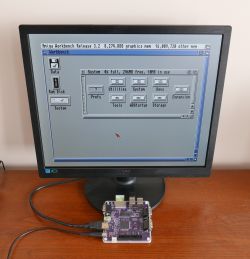
TL;DR: DIY-A586 packs a 100 × 100 mm Spartan-6 board that stores 30 FPGA cores in its 16 MB flash—“Up to 30 configurations in flash can be loaded” [Elektroda, piotr_go, post #18067213] Why it matters: one card swaps instantly between Amiga, PC-XT, C64 and more.
Quick Facts
• FPGA: Xilinx Spartan-6 XC6SLX9-2TQG144 [Elektroda, piotr_go, post #18067213]
• RAM: 8 MB SDR SDRAM @ ~56 MHz (Amiga) or 133 MHz CL2 (PC) [Elektroda, piotr_go, post #20583795]
• Flash: 16 MB SPI (Winbond 25Q128) — first flash needs external programmer [Elektroda, piotr_go, post #19143673]
• Power: 5 V via USB-C; legacy floppy drives need extra 12 V rail [Elektroda, EKBubba, post #19358582]
• SD: SDHC (≥4 GB) FAT32 + Amiga RDB, multi-disk driver v0.10 [Elektroda, piotr_go, post #20677771]
What components are mandatory for a working v1.6 board?
Essential parts: XC6SLX9 FPGA, AS4C4M16 SDRAM, Winbond 25Q128 flash, 16 MHz CMOS oscillator, SD socket, USB-C power jack, two SOT-223 LDOs (3.3 V & 1.2 V) and the HDMI level shifters [Elektroda, piotr_go, #18067213 #19178403].
Which SDRAM speed grade should I order?
Any 166 MHz (6 ns) IS42S16400J will run; Amiga core clocks the RAM at ~56 MHz and the PC core at up to 133 MHz CL2 [Elektroda, piotr_go, post #20583795]
How do I flash the board the first time?
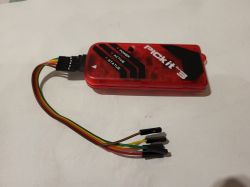
- Program the 25Q128 with “main v0.4.4” BIN at address 0x000000 using a CH341A or Arduino-SPI flasher [Elektroda, piotr_go, post #19143673]
- Solder the chip, short pins 7-8 on first boot if QuadEnable is unset [Elektroda, piotr_go, post #18234470]
- Afterwards update cores from SD with the F2 key.
My SD card isn’t recognised—what’s wrong?
The driver needs SDHC cards; old 2 GB SDSC cards fail detection [Elektroda, piotr_go, post #19186591] Format the primary partition FAT32 (MBR) and place *.A586 files in the root.
Can I use PFS3 or multiple virtual hard disks?
Yes. SD.ROM v0.10 adds multi-disk and PFS3 support. Each MBR primary partition type F0 becomes an Amiga unit; FAT volumes stay readable via fat95 [Elektroda, piotr_go, post #20677771]
How fast is the new Mikan 0.1.7 Amiga core?
It delivers ~143 % of real A500 CPU speed and triples SD throughput versus Minimig; audio, bitplane and copper bugs fixed [Elektroda, piotr_go, post #20783590]
Does Gotek or dual-drive work?
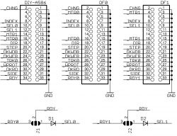
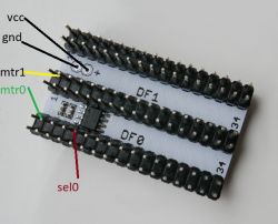
With Mikan v0.1.5+ the auto-switch logic makes DF1 the boot drive when it asserts _RDY during reset. Both drives must output _RDY and DF1 should be an emulator that ignores _MTR [Elektroda, piotr_go, post #20677771]
Edge-case: Amiga mouse and PS/2 mouse together?
From Mikan 0.1.9 you may connect either two Amiga mice (joy ports) or one PS/2 mouse; mixing beyond these combos is unsupported [Elektroda, piotr_go, post #21362045]
Why does my vintage Chinon floppy spin but not read?
Early 720 kB drives and A500 units draw 12 V for the spindle, which the DIY-A586 5 V rail can’t supply. Feed 12 V externally or use a modern 5 V-only mechanism [Elektroda, EKBubba, post #19358582]
Can the board emulate 68020 or AGA?
Not on an LX9. “FPGA too small” for AGA/020 cores, states the author [Elektroda, piotr_go, post #19738941]
How do I patch Kickstart 3.2.1 for SD boot?
Run the supplied xdelta script in mikan/kick3.x patch v0.8 then rename the output to KICK32SD.ROM and list it with -fb in bin2a586; checksum must match 75c85b… [Elektroda, piotr_go, post #19898942]
What’s the licence situation—why ‘DEMO LIMIT, 4 CORES MAX’?
Unregistered MAIN limits the flash menu to four cores; request a free personal key from the author via forum PM to unlock [Elektroda, tchernychov query #21048193 and piotr_go reply context].
Does the board support CRT 15 kHz output?
Yes. Set HDMI-to-VGA-to-SCART chain; core outputs 720×576 50 Hz RGB proven on a Thomson CRT [Elektroda, piotr_go, post #19213580]
Failure fact: What bricks PS/2 on cold start?
PS/2 lines could stay low; MAIN v0.4.4 adds a reset pulse that restores keyboard/mouse enumeration [Elektroda, piotr_go, post #20783590]
Where can I source the 16 MHz oscillator?
Use any 3.3 V CMOS clock module, e.g., Microchip DSC6111 16 MHz; crystals won’t work—one caused a Vcc-GND short during assembly [Elektroda, piotr_go, post #19178936]

