logo elektroda
logo elektroda
X
logo elektroda

T.amp TSA 4-1300 Power Amplifier Issue: Not Turning On, Red Diode Flashing, No Visible Damage

Matek920605 69336 346
ADVERTISEMENT
Treść została przetłumaczona polish » english Zobacz oryginalną wersję tematu
  • #121 18424880
    398216 Usunięty
    Level 43  
    kudlatyy1 wrote:
    good that on time I have traveled the regulator began to smoke
    If you were He came maybe he wouldn't start smoking?
  • ADVERTISEMENT
  • #122 18424898
    kudlatyy1
    Level 12  
    398216 Usunięty wrote:
    kudlatyy1 wrote:
    good that on time I have traveled the regulator began to smoke
    If you were He came maybe he wouldn't start smoking?

    Maybe not. Improved.
  • #123 18424903
    398216 Usunięty
    Level 43  
    kudlatyy1 wrote:
    Corrected.
    Thank you. Forgive me, but this one was the first one I noticed in your message.
  • #124 18427314
    Krzychu1843
    Level 12  
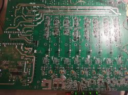
    I was able to sit down on the weekend, so here's my report - 2 channels already covered. Waking up was caused by a corrosive grommet leading to the R171 (I feel that in this copy I will have more such surprises because it turns out that it was lying somewhere in a damp room). There were the last 2 to be taken - the ones that were stoned. Have any of you figured out what the signal control at the end looks like? I mean the connections of opamps - because the outputs from those responsible for the burned out channels have 2 times lower amplitude of the output signal than the efficient ones (with the same input). I am posting the photo for which there was a request. Hope it helps :)

    T.amp TSA 4-1300 Power Amplifier Issue: Not Turning On, Red Diode Flashing, No Visible Damage
  • #125 18429408
    INtRO_Tech
    Level 14  
    Krzychu1843 - good job, one thing puzzles me - the converter for two IGBTs probably does not give full voltage to the trafo, because your measurements show that the maximum voltage available for the power amplifiers is 97V [H3] symmetrical, so the maximum power for this voltage is ~ 580W for 4 ohms, unless you don't know something :) .

    As for the op-amps - I did not have time to do this this week, but I have a similar problem (as described above) - constant 200mV on the CH2 output despite removing the CH2 power block and strange power supply - all op-amps +/- 15V a op -amp from the released + 15V / -12V channel, i.e. something shortens on this line. After removing the suspect op-amp, the power supply is still about this value, so it's not the op-amp's fault.

    A request for one more measurement - auxiliary voltages, if you could measure it, it would be great, I mean the +/- voltage on the conduits on the SMD bridge.

    Kind regards
  • #126 18431083
    Krzychu1843
    Level 12  
    Yes, the converter may not give full voltage (I also wrote that I do not know if it will help you :) ) but its value is quite enough to make the amplifier fully functional. From what I remember, the auxiliary voltages fluctuated within + - 13.8V for me. I am waiting for the electrolytes that are responsible for powering the opamps in the damaged channels (the original ones were really hot, so for the sake of peace, I prefer to replace them) and I will take a measurement. I will also put the voltages at the full converter, but I prefer to embrace the other channels first - it will hurt my pocket less than it shoots 2 igbt instead of 4 :P

    Added after 4 [minutes]:

    INtRO_Tech wrote:

    A request for one more measurement - auxiliary voltages, if you could measure it, it would be great, I mean the +/- voltage on the conduits on the SMD bridge.

    Do you mean measuring on capacitors after rectification from EF8 diodes? If so, the output from the capacitors is + -15V - even :)
  • ADVERTISEMENT
  • #127 18431249
    INtRO_Tech
    Level 14  
    Oh crap, +/- 15V? It's a bit strange because there are 7815 and 7915 on the way to opamps, they can function with such a low auxiliary power? Stupid question but I encountered different behavior of the 78xx series rulers when the power supply is too low.

    Regards
  • #128 18431355
    Krzychu1843
    Level 12  
    According to the documentation, it's true - there should be 2V more than the output, but it works - it gives the output what it gets at the input. Operational amplifiers do not have any problems when operating with a slightly low voltage, so there is no point in trying to mess around. Probably after bringing the inverter to the original, the supply voltage will increase (so the stabilizers will start working as they should).
  • ADVERTISEMENT
  • #129 18432896
    aaanteka
    Level 42  
    Krzychu1843 wrote:
    According to the documentation, it's true - there should be 2V more than the output, but it works - it gives the output what it gets at the input. Operational amplifiers do not have any problems when operating with a slightly low voltage, so there is no point in trying to mess around.

    Only that the stabilizer supplied with too low voltage does not stabilize, and what's more, it can oscillate and be the main load in a series connection of receivers (stabilizer and amplifiers). This course of action does not lead to anything good. With proper power supply, the system can work quite differently (read incorrectly).
    INtRO_Tech wrote:
    one thing makes me wonder - the inverter for two IGBTs probably does not give full voltage to the transformer,

    But isn't that a full-bridge configuration, gentlemen? How is it supposed to work properly with two transistors?
  • ADVERTISEMENT
  • #130 18433206
    Krzychu1843
    Level 12  
    And wherever I wrote earlier that it works properly :) It does not work and we are all aware of it, but the results of this work are sufficient to repair the channels (if someone is not able to connect an auxiliary power supply in the form of a trafa, you can do it anyway). As for the oscillations - yes, but if it were of great importance, the problem would appear on 4 channels, not only on 2. The most important thing is that the power supply should be symmetrical - the opamps will not be fussy - at least in my case.
  • #131 18433299
    aaanteka
    Level 42  
    Krzychu1843 wrote:
    It is not working and we are all aware of it, but the results of this work are sufficient to fix the sewers

    A very questionable point. In this amplifier, the converter works properly at the nominal load. What's more, if a colleague thinks that the amplifiers powered with +/- 160V can be checked with a voltage in the range of +/- 80-90V for the same operating points, then he is very wrong.
    This amplifier cannot be repaired like conventional 100-400W AB or even H rated designs.
    I would like to add that this is a budget construction deliberately designed for a lifetime of 1000-1500h of work with the use of a maximum of 60-70% of the nominal power, excluding work for bass channels.

    I admire my colleagues' enthusiasm, but I know from experience that repairing such damaged, overloaded amplifiers is impossible and not profitable. The problem is the rather delicate PCB circuit, which is overloaded and damaged. If we add bad environmental conditions to this, we have a complete picture of the damage.
    Even if it is possible to repair and fully start up such a copy, it will soon be damaged again, costly damage.

    Added after 3 [minutes]:

    Krzychu1843 wrote:
    As for the oscillations - yes, but if it were of great importance, the problem would appear on 4 channels, not only on 2. The most important thing is that the power supply should be symmetrical - the opamps will not be fussy - at least in my case.

    You are wrong, buddy, with asymmetrical supply circuits it is different. In general, every amplifier is susceptible to oscillation, except that not every amplifier has all parameters identical (only similar and with some tolerance).
    Assuming, like you, more than one died, contenting itself only with replacing damaged elements with new ones with the same designation. And the blame for his failure was described by the word "counterfeit".
  • #132 18434289
    Krzyk2
    Level 12  
    Hello everyone .
    Unfortunately, I have to join the topic.
    Well, the problem with this amplifier is that there are 6 versions of the discs, and thus each of the writers is right, but not entirely.
    This year I had the opportunity to make over 20 pieces of thomann phrases and unfortunately most of them were in the oldest version, i.e. ab or c where gp4066d transistors were almost 100w weaker, only in newer ones they were corrected for correct versions, unfortunately in Poland in stores it's a lottery because they are sold as correct and in practice the old type.
    The correct information is only provided on the collective packaging.
    Even at TME it turned out that they had weaker ones and they shot.
    What's more, most of the LEDs in the series have a 5 ohm smd resistor in the improved version, which are physically larger than their predecessors, hence the amplifiers could work for years and some moments and buzz.
    The versions can also be identified by the jumpers at the amplifier output near the Speakon.
  • #133 18434389
    aaanteka
    Level 42  
    Krzyk2 wrote:
    Well, the problem with this amplifier is that there are 6 versions of the discs, and thus each of the writers is right, but not entirely

    Namely, in what aspect? And I don't really understand how this has to do with how to properly diagnose the fault?
    Krzyk2 wrote:
    where the gp4066d transistors were almost 100w weaker, only in newer ones they were corrected,
    There are no gp40066d transistors while there are IRGP4066D and former AUIRGP4066D1 (still available from some distributors). And what is this nonsense you write about the weaker versions of the IRGP4066D, what is it? Is there any manufacturer's note, or is it just your guess?
    The characteristics of the transistor "Maximum DC Collector Current vs. Case Temperature", "Power Dissipation vs. Case Temperature" and "Forward SOA TC = 25 ° C, TJ
  • #134 18434431
    Krzyk2
    Level 12  
    Typo IRGP4066D, generally described as GP4066D, however, the rest of the transistor is important, i.e. IRGP4066D-EPBF and it was used in this longest-lived version. As for the lifetime, I agree with you that it is short, but what to expect in an oven that is not adapted to continuous operation to drive bass, as most do, not to mention the fact that it is a bit lacking for nominal power.
  • #135 18434510
    aaanteka
    Level 42  
    Krzyk2 wrote:
    the rest of the transistor is important, i.e. IRGP4066D-EPBF

    Oh, buddy, you are writing without knowing what, maybe important from the point of view of ecology.
    It does not matter what the electrical parameters of the transistor are. PBF, or rather PbF, stands for Pb Free, meaning no lead, lead free. )
    Krzyk2 wrote:
    Nothing when it comes to durability, I agree with you that it is short, but what to expect in an oven that is not adapted to continuous operation to drive bass

    This amplifier is completely unsuitable for the bass channel, because its purpose, like most such constructions, was to be used with monitor channels, vocals, medium and high band satellites.

    Added after 16 [minutes]:

    T.amp TSA 4-1300 Power Amplifier Issue: Not Turning On, Red Diode Flashing, No Visible Damage
  • #136 18434785
    Krzyk2
    Level 12  
    I think that help is more important on this forum, not hate, buddy.
    I order collective packaging for electronic components and unfortunately they can technically differ from what the catalog writes, hence the price spread in stores that do not pay attention to it.
    You are probably a more experienced electronics technician and he does not deny it, but sometimes it is worth helping instead of criticizing and killing the topic and this is what will happen with this post, approaching it in your style.
  • #137 18435191
    aaanteka
    Level 42  
    Buddy, buddy, you write nonsense that the transistor made in lead-free technology has other parameters, more precisely it applies only to the coating - tinning of the transistor leads and you call it hate?
    Think about it and by the way recall the rules of this forum. Who is the "hatter" here?

    Added after 2 [minutes]:

    Krzyk2 wrote:
    This year I had the opportunity to make over 20 pieces of thomann phrases and unfortunately most of them were in version the oldest, i.e. and b or c where the transistors gp4066d was almost 100w weaker only in the newer versions they were corrected for correct versions, unfortunately in Poland in shops it is a lottery because they are sold as correct and in practice the old type.
    The correct information is only provided on the collective packaging .
    Even at TME it turned out that they had weaker ones and they shot.

    The mysterious parameters of the 100W weaker mysterious transistor, the mysterious versions of the a, b and c amplifiers bring something substantive to the conversation about the diagnosis and how to fix the fault?
    I will ask again: - where did you read it in what application note and as what characteristic parameter?
  • #138 18435401
    Q-mac
    Level 27  
    Reading the posts in the topic, he concludes that the failure of the power supply is directly due to the failure of the amplifier. In the event of a short circuit in the power supply line and no short-circuit protection, even the most powerful transistors in the power supply will not help ...
  • #139 18435486
    aaanteka
    Level 42  
    Exactly, what's more, it is 4 amplifiers powered from one power supply. The system has not been refined in terms of variable load within fairly large limits with high dynamics of variability. In addition, the transistors used in the power supply are poorly selected on the verge of exceeding several key parameters, including: the allowable power loss for a given operating point, operating voltage. The mechanical design is also very poorly refined, in general the amplifier is too densely packed in the volume of the housing with the lack of symmetry of heat dissipation to the environment and the lack of symmetry of the heating elements. The amplifier is a perfect example of how not to design and how component boundaries can be misinterpreted. In addition, overuse is not in accordance with the intended use and the failure is only a matter of time.
  • #140 18439375
    kudlatyy1
    Level 12  
    That's why I gave up on the repair, I will use the housing and blocks to make another four-channel amplifier. A question for those who have something else working in this amplifier, what is the voltage to power the board from the drive indicator.
  • #141 18439852
    aaanteka
    Level 42  
    kudlatyy1 wrote:
    That's why I gave up on the repair, I will use the housing and blocks to make another four-channel amplifier

    And you realize that when it is to be used in public places, you are obliged to repaint the housing and permanently remove the company's logo and all production markings?

    However, civil liability remains in the case of the use of this non-certified sound equipment where third parties are involved. You can not badly develop the status of a criminal with such modernizations.

    The problem is not only how you use this device only for your own use at home, but such an amplifier at home, for your own use - a questionable matter.

    On the other hand, it was mentioned earlier: - A 4-channel (universal) stage amplifier in such a cubature is a bad idea. Even renowned producers have withdrawn from this trend.
    Four separate heat sinks and it gets too tight and difficult to evenly flow air, even forced. Two heat sinks with two channels on one heat sink becomes a problem with uneven load of channels, and the user can additionally complicate the matter - never follow the recommendations in the instructions for a specific purpose in given connection configurations.
  • #142 18439898
    398216 Usunięty
    Level 43  
    aaanteka -> Dear friend, why such sorcery?
    aaanteka wrote:
    However, civil liability remains in the case of the use of this non-certified sound equipment where third parties are involved. You can not badly develop the status of a criminal with such modernizations.
  • #143 18505704
    ziro_9
    Level 10  
    Hello,
    I haven't been here for a long time and I don't know if any of you are still fighting with this power amp.
    Some time ago I managed to repair my copy.

    I performed the first start on a 4A circuit breaker with a delay C.
    The voltages on individual stages (measured at 230VAC ZAS) are:
    P + - 30V
    1H + - 62V
    2H + - 125V
    3H + - 188V
    Power consumption at start-up is approximately 600W (not measured exactly)
    Idle power consumption 89W

    Indicative list of damaged elements:

    * From the power supply:
    -IGBT pair
    -47R resistors before gates of damaged IGBTs
    -Diodes (1N4148W) in front of IGBT gates
    -15V zener diodes protecting IGBT gates
    - IR2110S gate driver
    - GBU2506SF rectifier bridge

    * From the amplifier:
    - A pair of transistors (NJW0302G and NJW0281G)
    - Output relay

    If anyone has any questions regarding the repair of this series, please feel free to ask them, maybe I will help you somehow.
    Regards.
  • #144 18505716
    INtRO_Tech
    Level 14  
    Hello,

    Congratulations to you!

    So far I have fought, but now they are lying and blooming due to lack of time, but I'm going to get to them in the near future.

    This zenerka is specific or ordinary?

    On the amp side, I still have a damaged preamplifier, so a bit more work.

    Kind regards
  • #145 18505738
    ziro_9
    Level 10  
    Hello,
    As for the zener diode, I used MMSZ5245BT1G.
    When repairing the amplifier stage, I initially worked at P + -25V and 1H + - 20V.
    As for the problem with the preamplifier, how did it appear to you?
    Regards.
  • #146 18505748
    INtRO_Tech
    Level 14  
    Hello,

    It is shown by a glowing orange LED on the amp board regardless of the signal input, it is possible that the reason for this state is the lack of power stages from this channel, they are desoldered.

    Regards
  • #147 18505833
    ziro_9
    Level 10  
    Probably, as you wrote yourself, the orange LED lights up due to the lack of terminal transistors.
    When you find time, try to solder both pairs of KB transistors and at least one pair of NJW and the diodes next to the keying transistors.
    And write what appears on the output of the channel.
    What is this channel number?
    Regards.
  • #148 18505852
    INtRO_Tech
    Level 14  
    Hello,

    For me, it's the second channel, it's possible that you're right, a channel without a power block can go silly.

    And you managed to decode the T4 and T5 LEDs? Ie. They have such markings on the housings.

    Regards
  • #149 18505939
    ziro_9
    Level 10  
    Hello,
    The T4 diode is the equivalent of the 1N4148 switching diode in SMD, i.e. 1N4148W
    The T5 diode, and you probably mean the H5 diode. It is the equivalent of a 15V 0.5W Zener diode in SMD, i.e. MMSZ5245BT1G
    Regards.
  • #150 18506081
    kudlatyy1
    Level 12  
    I gave up, I bought two-channel modules from the Chinese, two pieces, 60v power supply and 300 watt power and now the question is whether a 1500 watt converter is enough ?. As if someone would need some parts to write boldly.

Topic summary

The discussion revolves around issues with the T.amp TSA 4-1300 power amplifier, specifically its failure to turn on, indicated by a flashing red diode and no visible damage. Users share their experiences troubleshooting the amplifier, including checking the power supply, replacing damaged components like IGBTs, IR2110 drivers, and capacitors, and the challenges of finding schematics. The conversation highlights the importance of proper voltage levels, the need for fuses to prevent damage, and the potential for modifications to improve reliability. Several users report successful repairs after replacing critical components and adjusting the power supply configuration.
Summary generated by the language model.
ADVERTISEMENT