logo elektroda
logo elektroda
X
logo elektroda

T.amp TSA 4-1300 Power Amplifier Issue: Not Turning On, Red Diode Flashing, No Visible Damage

Matek920605 71136 346
ADVERTISEMENT
Treść została przetłumaczona polish » english Zobacz oryginalną wersję tematu
  • #91 18381400
    Michel424
    Level 14  
    Congratulations on the progress, but the damaged duct needs to be repaired so that there is no need to worry about it and continue to carve the converters ...
  • ADVERTISEMENT
  • #92 18382624
    Matek920605
    Level 10  
    I have a little riddle, I got the IRGP 4066D transistors as they were installed in the amplifier, they are new. After checking with a tester, it shows me as a diode and a resistor. I also have second new transistors marked GP4066D and the tester shows me as a transistor, exactly as in the catalog. Are those with the designation IRGP4066D any fake? Should the tester indicate this?
  • #93 18382650
    398216 Usunięty
    Level 43  
    Matek920605 wrote:
    Should the tester indicate this?
    The tester is only a tester - and as "smart" as the one who wrote the program to run it. Many testers cannot check such transistors correctly and show various (!) Stupid things.
  • #94 18383188
    INtRO_Tech
    Level 14  
    Hello,

    Such a small attention when repairing - when you run this amplifier on a table without a housing, you have to connect the bolt points with each other, this design uses the housing as a connection of the ground points, without that, terrible stupid works and everything goes crazy. Today I started the amplifier on the auxiliary power supply and normally I can listen to music on it, of course I do not have full power :)

    T.amp TSA 4-1300 Power Amplifier Issue: Not Turning On, Red Diode Flashing, No Visible Damage

    Added after 59 [minutes]:

    The only problem I have is the clip on CH2 still glowing (previously I removed all the transistors from this channel because some of them were compacted and I did not need them for testing).

    I probably have something else released on this channel because I have 0.95V DC at the CH2 output, so the relays do not want to turn on and FAULT is still on. Of course, I checked the sound on an artificially shortened relay.

    I removed the preamplifier, but the DC is still there, in general all the preamps get a nice 15V symmetrical and in place of the CH2 preamp I have - 12V and + 15V, that's what I was able to dig out.
  • #95 18384356
    Michel424
    Level 14  
    Okay, but all the time on a different power supply or have you already put together converters? This is one more channel that will probably not be as big a problem as the converter
  • #96 18386817
    kudlatyy1
    Level 12  
    And what is the power supply on the second stage? Because I think so, to use some power on the inverter from the Chinese, there is a lot of it on Aliexpress.
  • ADVERTISEMENT
  • #97 18390032
    Matek920605
    Level 10  
    Where is the best place to buy SG3525A? In my area, electronic stores or coal do not have this system in this housing or you have to wait a month for a shipment from China: /
  • #98 18393793
    Matek920605
    Level 10  
    I checked the entire system at viper22a, all smd elements are working. Without the SG3525a and IR2110s, I turned on the amplifier and the diode on the board is flashing and I can hear a pulsating sound from the Viper22a. I installed the new IR2110s and SG3525a, turned on the amplifier for a while and now you can hear that the viper hums loudly, but nothing else is happening. You can hear this noise and the LED on the disc is lit all the time. I also gave the current from the 12v converter to these points and nothing happened with the converter, the viper22a showed 12v

    Added after 31 [minutes]:

    After a long while it started working, but still crashes the IGBT. All diodes were replaced, SG3525, IR2110S, resistors checked and working.
  • #99 18394153
    popej
    Level 13  
    from what I read you write that in smd you have everything working, I have this tip disconnected and under the fired igbt I have broken diodes and resistors that are connected in parallel is it d208 and r476, d207 and r475 are you working?
  • #100 18394177
    Matek920605
    Level 10  
    Yes, these diodes were changed before IGBT re-fired with new ones, I had the resistors working
  • #101 18394290
    popej
    Level 13  
    I traveled it all in turn and after what you described, I found only a damaged bridge br3, specifically 2506SF, pierced towards + and then stabilizers + -15 and one pair of transistors in channel A

    Added after 6 [minutes]:

    I still have a question, how do you put on heat sinks and these clamps? :D because I already have plans to do it with screws because I don't have an idea in a month until the parts come, because I can't see me paying 10 times punctured in Polish stores, but it would be useful to know it in advance
  • #102 18394674
    Matek920605
    Level 10  
    I put these clips on the removed heat sink. When mounted on a plate, it is very hard to press in order not to damage the plate. Unless you have some special tongs for this. I also had a couple of transistors passed on the first channel.

    Added after 30 [minutes]:

    I even thought to throw out 2 channels from this amplifier and omit all this power, throwing out 2 channels we have a lot of free space, where you could put some transformers and mount the power for the other 2 channels. Then it would be a 2 channel amplifier. But I don't know if this idea would work efficiently and if such a modification would be pointless or would be profitable
  • #103 18394919
    Michel424
    Level 14  
    Rather moderately profitable because the idea behind this end is different. The best option would be to change the power supply of this amplifier. Only making such a converter is certainly not easy, someone with a lot of knowledge would have to embrace it so that there would be no such adventures later as in this case.
  • #104 18394940
    popej
    Level 13  
    well, even if you picked up this housing and put enough transformer on the top plate, you would have to carry it in two
  • #105 18394971
    Michel424
    Level 14  
    Include that 20kg, so converters either reaninate or make a new one.
  • #106 18396295
    Michel424
    Level 14  
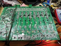
    I'm going, it will seem trivial but I advise you to check all the paths because see what happened to me. All possible transistors present in the amplifier have breakdown ... And many paths are missing. T.amp TSA 4-1300 Power Amplifier Issue: Not Turning On, Red Diode Flashing, No Visible Damage T.amp TSA 4-1300 Power Amplifier Issue: Not Turning On, Red Diode Flashing, No Visible Damage
  • ADVERTISEMENT
  • #108 18396615
    Michel424
    Level 14  
    Fortunately, I can return my amplifier and it will do it, because there is no point in doing it.
  • #109 18401504
    INtRO_Tech
    Level 14  
    Hello,

    I received the second piece of this amplifier ..... and the first thing I did was the measurements of the power transistors, of course damaged as in the predecessor, channel 2 (I have two more of this amp, if I find time, I will also disassemble them and give a report ).

    I desoldered the entire CH2 power block and fired the impulse transformer to connect my test power supply to the secondary windings as in the predecessor (2x12V AC) and the end of course does not fire, it turned out that the 7815 and one of the preamplifiers (from the SMD side, the lower right part of the board, when the inverter is on the left). In the predecessor, everything on this line, except for the released CH2 power block, was approx.

    After taming the problem, connecting the ground points, and adding voltage to the final stages (class H - first stage), it turned out that I still have a short circuit on the positive branch.

    I have a limited time in the week for further fun, because I "spread out" with a good friend with this mess, but my conclusions about a reasonable repair are:

    - Before repairing the converter, check the terminal transistors for punctures, if they are to - remove the entire power block from this channel (two complete element heat sinks) for the duration of the repair,

    - Fix the end of the power from faults such as: short circuits, paths, lack of mass, and on low power for H1 / H2 and H3 (gradually adding 2x12AC), bring it to the operating state,

    - After these steps, repair the inverter.

    Otherwise it does not make sense, it will trigger the IGBT because despite the removal of the output transistors, we can still have faults in other elements.

    When the power amplifier is on the test power supply, then try to repair the converter, otherwise it is a waste of money, the amplifier has no protection between the converter and the power amplifiers, when there is a short circuit = full power goes and the IGBTs are contacted in it.

    Regards
  • #110 18407708
    kudlatyy1
    Level 12  
    I also have broken paths, probably the first channel to be dismantled. Would anyone draw me up on how to connect without the original power supply? I'm not an electronics engineer, but maybe with your help I would revive him.
  • #111 18409744
    ziro_9
    Level 10  
    Hello,
    Some time ago this power amplifier came to me.
    After removing the casing, at first glance, the following were damaged:
    - 3 transistors in the final stage of the fourth channel (Overload)
    - IGBT pair (IRGP4066D) (Overload)
    - BR3 rectifier bridge (GBU2506SF) (The short-circuit current is deposited on it with the most common failure of this terminal, which is the breakdown of the end transistors)
    - IR2110A and SG3525A
    - resistor limiting the current going to the voltage regulator (R134)
    - LEDs on the IGBT control line

    At first glance, that's it. I will continue to act when I have some time for it.

    kudlatyy1 wrote:
    Would anyone draw me up on how to connect without the original power supply? I'm not an electronics engineer, but maybe with your help I would revive him.


    To run the tip on the replacement power supply for the first time, you need to do:
    - first, choose pierced terminal transistors
    - see post # 94 on this topic
    - unsolder the impulse transformer and connect a symmetrical auxiliary power supply in its place (15VAC is enough)
    - be sure to check the BR3 bridge and the D273, D272, D274, D275, D194, D196 rectifier diodes.
    - connect "in the air" control panel
    - start the auxiliary power supply and verify the voltages on the voltage regulators.
    - When everything is ok, you connect the H-1 (main) symmetrical 15VAC or 24VAC power supply (better to start with the lower one)
    - you verify the presence of DC voltage at the output
    - if it's ok up to now, give the signal from the generator to the amplifier and see if the channel is OK. The best is an oscilloscope with an artificial load, or a loudspeaker, and you test it by hearing. This test requires a heat sink on the tested channel.

    Ideally, you should provide clear photos of the tip plate as you may have a different version and a slightly different connection layout. I would also like to have a look at the connection failure in the inverter.

    What replacement should be used for the GBU2506SF bridge? It is an ultra fast bridge, the usual ones will not work.

    Regards.
  • #112 18411580
    Krzychu1843
    Level 12  
    Fortunately, I was able to move the converter - although it does not have full power (it only works on 2 transistors), it is enough to cover the channels. In my free time I will give you a detailed list of things that I had to replace, but from what I only remember briefly, it is worth paying attention to (as my colleagues wrote above) passive elements near transistors - diodes, resistors and capacitors. In addition to the released drivers, I also flew LM339 (+ one t4 diode next to it) and LM555 - maybe they got an arrow from Viper, who knows :) . Unfortunately, my copy is not funny when it comes to channels. 2 do not get up at all, 1 plays but crap (photo of the graph taken from the collector), the last one is operational. One of you had such a problem with this tip. I checked the op-amps - they are functional - only at the output of one (marked on the pcb as IC3, there is a distortion and I have no idea where from and for 2 days I am running the oscilloscope around the entire circuit). T.amp TSA 4-1300 Power Amplifier Issue: Not Turning On, Red Diode Flashing, No Visible Damage
  • #113 18411832
    kudlatyy1
    Level 12  
    Today I also buried a little and so:
    -IGBT fired (broken lines on laminate) but not fired
    - one pair on the first channel (the one from the converter) is out of order
    - two bridges in working order (APT60DQ60BG diodes have not been checked yet).
    I desoldered the trafo, I desoldered the entire channel out of order, I gave a symmetrical DC auxiliary voltage of about 18 V behind the bridge and smd diodes, the grounds are shorted, the orange leds are on, which are poorly visible, because there is a shirt on them, probably to make it tight not offended (see photo). After applying the AC voltage in front of the bridge, as shown by ziro_9 in the photo, the diodes do not burn anymore. I suspect the smd diodes are released. Question for ziro_9:
    - I do not know how to verify the voltages on the voltage regulators after applying auxiliary power
    -Do the auxiliary AC connect as in the picture? i.e. three gnd points? because your cables go somehow different.
  • #114 18413207
    ziro_9
    Level 10  
    kudlatyy1 wrote:
    should auxiliary AC connect as in the picture? i.e. three gnd points? because your cables go somehow differently.


    In the photo provided, the auxiliary voltage is marked with black arrows (the description above the arrows is assigned to the arrows). In turn the red, or "main", is the basic supply voltage of the final stage. The mass is shared. Orange LEDs have two functions. They are CLIP and ERROR indicator as there is something wrong with the final grade. In your case, the LEDs were on because the final stage had no primary power.

    kudlatyy1 wrote:
    I do not know how to verify the voltages on the voltage regulators after applying auxiliary power


    You measure the voltage between the marked point (one and then the other) in the photo below and ground. Indications should be max 15V and -15V. They can be unbalanced and lower due to the lack of power supply to the final stage.

    But here we will not find out too much, first you need to give the "main" power supply (symmetrical 15VAC or 24VAC) and test the end as AB class.
    After that you must:
    - check the presence of DC voltage at the terminal output (measure e.g. against the mass, and with the foot from the output coil),
    - verify voltages on regulators and MC33078 operational amplifiers,
    - if the orange LED in a given channel goes out, you can try to test it,
    - you can connect the load, give the signal and check if the given channel works
  • ADVERTISEMENT
  • #115 18414071
    kudlatyy1
    Level 12  
    Thanks to the entries ziro_9, today I was able to run channels A and B on the auxiliary power supply, but the relays did not turn on at 15VAC, after applying 24VDC it started and the LEDs on them went out. I suppose 18VAC would be just right. The voltage regulators showed + -7VAC at a lower power supply, and at 24 + -15. Channel C got hot (one rail), there is a short circuit somewhere. All elements on the heat sink are functional (it seems to me after measurements). After desoldering channel C, the power ends A and B started. And I would forget, on channel C, despite the lack of terminal transistors, the led blinks, and on channel D it lights. I don't know where to look for the reason now. Thanks to ziro_9. And another question: is it possible to run a channel without one pair of output transistors?
  • #116 18417057
    ziro_9
    Level 10  
    kudlatyy1 wrote:
    can I run a channel without one pair of output transistors?


    This can be done to test a given channel if it works, there will be a bit greater voltage drops on the transistors. You can test even on one pair, only the transistors must be refilled after all, because the channel will not reach its power parameters.

    Krzychu1843 wrote:
    Unfortunately, my copy is not funny when it comes to channels. 2 don't get up at all


    CLIP indicators are "lit"? Constant output voltage? Protect keeps relays and FAULT? Can you say more about it?
    Can you measure and share with us information what are the values of individual voltages supplying this power amplifier?
    How often does the PSU work? Did you have the GBU2506SF bridge burnt? What replacement did you use?
    If I find some time, I will try to run the tip on the replacement power supply and I need the voltage values.
  • #117 18417528
    Krzychu1843
    Level 12  
    Something is mixed up quite a bit, because the fault is lit all the time on all 4 channels - it seems to me that the key to solving this problem is embracing this "arousing" output. When I desoldered the thermal sensor from this channel, the faulty went out nicely (it is worth adding that in this channel - ch4 the voltage value given to the sensor is lower than the rest). I do not know if this will help you (because I do not have 4 of these transistors, so I will not fire with the full power of the converter - I will have fun with it when the channels are operational) but the voltage (looking at the bottom of the board from the side where the relays are located) ) in turn they look like this: + ok97V (ranges from 96.5 to 96.9 but maybe it's the fault of the meter), + 31.5V; -97V; -64V; -31.5V; + 64V.
    The converter works at a frequency of about 85kHz.
    Returning to the topic of damaged channels - the constant output is within 100mV, so it could be worse :) Fortunately, my bridge survived, but you have to choose something from ultra fast bridges (and if it is not of such power, convert it to diodes).
    Yesterday I wrote to the Chinese distributor of these amplifiers (records that are packed in new t.amp kennels) - one distributor told me to wait because he had to contact the engineers department and the other asked for photos showing the defect (I sent graphs collected with an oscilloscope) and silence ... contact broke off :(
  • #118 18417621
    INtRO_Tech
    Level 14  
    Krzychu1843 wrote:
    Something is mixed up quite a bit, because the fault is lit all the time on all 4 channels - it seems to me that the key to solving this problem is embracing this "arousing" output. When I desoldered the thermal sensor from this channel, the faulty went out nicely (it is worth adding that in this channel - ch4 the voltage value given to the sensor is lower than the rest). I do not know if this will help you (because I do not have 4 of these transistors, so I will not fire with the full power of the converter - I will have fun with it when the channels are operational) but the voltage (looking at the bottom of the board from the side where the relays are located) ) in turn they look like this: + ok97V (ranges from 96.5 to 96.9 but maybe it's the fault of the meter), + 31.5V; -97V; -64V; -31.5V; + 64V.
    The converter works at a frequency of about 85kHz.
    Returning to the topic of damaged channels - the constant output is within 100mV, so it could be worse :) Fortunately, my bridge survived, but you have to choose something from ultra fast bridges (and if it is not of such power, convert it to diodes).
    Yesterday I wrote to the Chinese distributor of these amplifiers (records that are packed in new t.amp kennels) - one distributor told me to wait because he had to contact the engineers department and the other asked for photos showing the defect (I sent graphs collected with an oscilloscope) and silence ... contact broke off :(


    Are you able to put these tensions on the picture of the plate with paint? It would be very helpful :)

    For now, I am facing a fight due to lack of time - the next steps I want to take are checking the preamplifiers,

    As for China - I wrote the same - I sent photos, a list of damaged elements - broken contact.

    Kind regards
  • #119 18417669
    kudlatyy1
    Level 12  
    [quote = "Krzychu1843"]
    Something is mixed up quite a bit, because the fault is lit all the time on all 4 channels - it seems to me that the key to solving this problem is embracing this "arousing" output. When I desoldered the thermal sensor from this channel, the faulty went out nicely (it is worth adding that in this channel - ch4 the voltage value given to the sensor is lower than the rest).

    In my case, the fault does not shine on working channels, as soon as I solder the third channel, it heats up and all the yellow ones glow. Tomorrow I will try to throw the fourth channel without a pair, we'll see what will happen. On the third, everything seems to be working, I don't know where to look for the reason. I don't like the kse340 measurement, the w diode shows about 900 mv.
  • #120 18424868
    kudlatyy1
    Level 12  
    However, on the third, the faulty kse, replaced with mje, the channel does not heat up and the fault is still lit, I left it on for about half an hour, the regulator on the negative bus started to smoke. Today, after replacing the plus and minus regulators, I have some strange voltages on them, the power supply is 24 VAC, the bridge is 18VDC, and the regulators only 12. Short circuit or smd bridge? I still have to replace the gp105n15, I just do not know what replacement to use.

Topic summary

The T.amp TSA 4-1300 power amplifier exhibits a failure to power on, with a flashing red diode near the capacitors and no visible physical damage. Investigation revealed multiple damaged IRGP4066D IGBT transistors on the primary side inverter, along with damaged power transistors (NJW0302GC), MOSFETs (GP105N15M), rectifier bridges (GBJ3006SF, 2506SF), and driver ICs (IR2110S, SG3525A). The amplifier uses a full-bridge power supply topology operating around 85-100 kHz with multiple symmetrical voltage rails (+/-15V, +/-40V, +/-60V, +/-90V, +/-160V) for preamplifier and power amplifier stages. The power supply design lacks galvanic isolation, current limiting, and effective overload protection, leading to frequent IGBT and associated component failures. SMD components such as EF8 and T4/H5 diodes (likely Schottky and Zener types) near the inverter and driver circuits are critical and often damaged. The triac (BTA41-600B) controlling AC mains to the rectifier bridge is also a common failure point. Repair attempts require replacing IGBTs, driver ICs, rectifiers, and passive components, but without a schematic or service manual, troubleshooting is challenging. Oscilloscope measurements of PWM signals and gate drive waveforms are essential for diagnosing dead time and control issues. Some users suggest replacing the entire power supply with a custom design due to the amplifier’s complex and failure-prone power stage. The amplifier chassis serves as a ground connection, which must be properly connected during bench testing. Auxiliary power supplies (e.g., 2x12V AC transformers) are used to test amplifier channels independently. Despite extensive repairs, issues such as persistent fault LEDs, relay non-activation, and channel-specific transistor failures remain common. The amplifier is considered difficult to service due to integrated power and control boards, lack of documentation, and complex SMD circuitry. The original design is reportedly based on the Chinese Leicozic DP41200 amplifier. Community consensus highlights the need for careful component verification, replacement of damaged SMD diodes and resistors, and cautious startup procedures using current-limited power supplies or light bulbs to prevent repeated damage.
Summary generated by the language model.
ADVERTISEMENT