These bulbs are dirt cheap Tuya bulbs (I get them in a 12-pack off of Amazon for between $4 and $5 per bulb, a very reasonable price for bright RGBCW bulbs), and I discovered to my delight that they're OTA flashable using the tuya-cloudcutter exploit. I'll start with notes about the various configurations I used for tuya-cloudcutter and OpenBeken, and then move on to the hardware teardown.
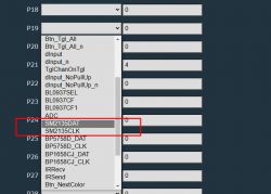
In tuya-cloudcutter, the device profile "Tuya-Generic/E27-RGBCW-Smart-Life-WB2L_M1" works fantastically. The chipset is BK7231N; flash an OpenBeken firmware designed for that chipset. In OpenBeken, the necessary module setup is to make P7 BP5758D_CLK, and P8 BP5758D_DAT. Additionally the channels needed remapping, so I added in the startup command "BP5758D_Map 2 1 0 4 5". This information is enough to get these bulbs nicely out of the Tuya dungeon and working great on open-source local-control firmware without having to do any hardware surgery.
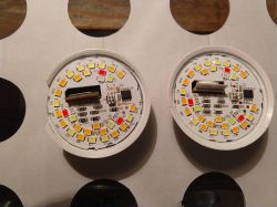
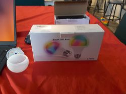
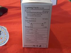
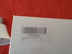
Over on an OpenBeken issue I opened, they recommended I post a teardown of this hitherto unknown device, and I had one bricked bulb (onto which I had carelessly flashed a BK7231T firmware) and another I had taken the dome off of and expected to sacrifice. First, some pictures of completely unaltered bulbs:
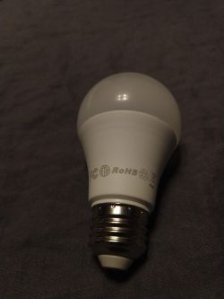
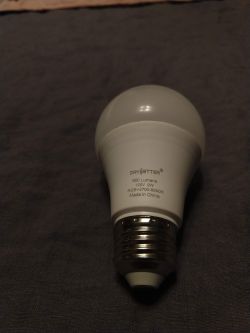
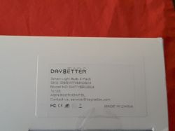
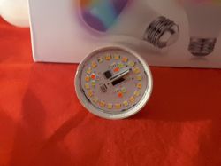
They don't really have any model name or number beyond the extensive descriptive text on the bulbs. The translucent dome is glued on and comes off with a bit of heavy-duty twisting and squeezing. Once removed, the light PCB and the tip of the MCU PCB are visible, as is usually the case:
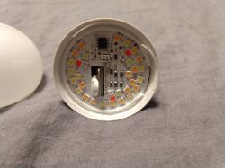
This board has 15 warm-white LEDs, 10 cool-white LEDs, and 3 LEDs in each of red, blue, and green. The most significant other components are that IC which is identified by the silkscreen as a BP5758, and a four-pin connector which transmits data and power from the MCU PCB (note that this differs from a lot of bulb teardowns --- 6-pin connectors are much more common!). Based on closer inspection later, I believe the pin closest to the BP5758 (the one on the upper left in the picture above) carries the BP5758 clock signal, the one close to both the BP5758 and the surface-mount resistor (upper right) carries 120V DC power, the one closest to the MCU cutout (lower left) is BP5758 data, and the one close to the cluster of resistors (lower right) is ground. At one point I was trying to determine which pins carried voltage and how much and accidentally shorted out the 120V and ground pins. This killed the bulb and the physical damage is visible in a later photo.
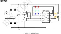
This board's schematic seems to be extremely close to one found in a Chinese-language report from a expo showing off Tuya bulbs which served as Bluetooth beacons.
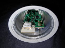
Disassembling the bulb further required taking off a lot of glue. The light PCB was glued down around the edges, and there was also an enormous glob of glue holding the MCU onto the LED PCB (seen in the photo above. The large glue-glob was easy to cut, and the glue around the edges succumbed to light but consistent upwards prying around the edges of the light board. Removal of this PCB allowed a glimpse of the interior:
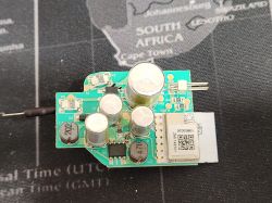
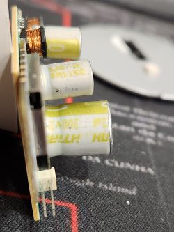
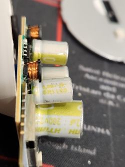
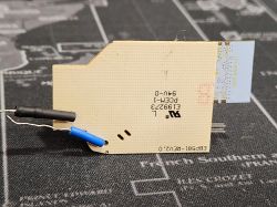
This board gets a better picture after the physical destruction of the bulb base. It was, as expected, connected to the Edison screw for power by two wires, one of which was an unsoldered contact with the screw wall; the other was soldered onto the button at the bottom. The plastic around the base of the screw was cut until it was possible to take the screw base and the PCB out, whereupon the full PCB, along with its connections to the Edison base, could be photographed.
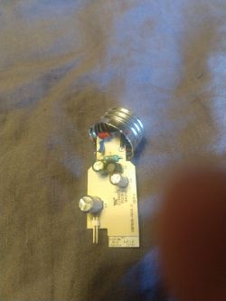
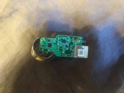
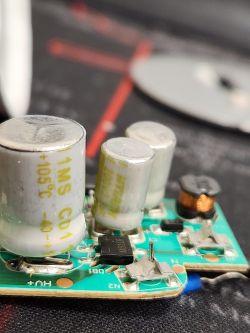
Most of what is on here appears to be power-supply stuff. The 4-pin IC on the narrow end is a rectifier with, as far as I can tell, no silkscreen. The 4-pin IC in the wider section is labeled as a KP35026, which seems to be a 3.3V power-supply. The scorch mark directly below the left side of the ICU shows where my careless short seems to have caused a SMD resistor to explode.
The MCU itself is labeled as a CB2L, which is a pretty standard Tuya Wifi unit built around a BK7231N chipset. As far as I can tell, pins P6, P26, and P24 are not used at all; P7 and P8 have traces to the LED-board connection.
AFAICT, this is mostly a pretty ordinary 5-channel bulb using a BP5758 for current control. It has the exact same configuration as a Nous P3, and as far as I can tell most of the same hardware although the physical layout on the PCB is a bit different.
In tuya-cloudcutter, the device profile "Tuya-Generic/E27-RGBCW-Smart-Life-WB2L_M1" works fantastically. The chipset is BK7231N; flash an OpenBeken firmware designed for that chipset. In OpenBeken, the necessary module setup is to make P7 BP5758D_CLK, and P8 BP5758D_DAT. Additionally the channels needed remapping, so I added in the startup command "BP5758D_Map 2 1 0 4 5". This information is enough to get these bulbs nicely out of the Tuya dungeon and working great on open-source local-control firmware without having to do any hardware surgery.
Over on an OpenBeken issue I opened, they recommended I post a teardown of this hitherto unknown device, and I had one bricked bulb (onto which I had carelessly flashed a BK7231T firmware) and another I had taken the dome off of and expected to sacrifice. First, some pictures of completely unaltered bulbs:


They don't really have any model name or number beyond the extensive descriptive text on the bulbs. The translucent dome is glued on and comes off with a bit of heavy-duty twisting and squeezing. Once removed, the light PCB and the tip of the MCU PCB are visible, as is usually the case:

This board has 15 warm-white LEDs, 10 cool-white LEDs, and 3 LEDs in each of red, blue, and green. The most significant other components are that IC which is identified by the silkscreen as a BP5758, and a four-pin connector which transmits data and power from the MCU PCB (note that this differs from a lot of bulb teardowns --- 6-pin connectors are much more common!). Based on closer inspection later, I believe the pin closest to the BP5758 (the one on the upper left in the picture above) carries the BP5758 clock signal, the one close to both the BP5758 and the surface-mount resistor (upper right) carries 120V DC power, the one closest to the MCU cutout (lower left) is BP5758 data, and the one close to the cluster of resistors (lower right) is ground. At one point I was trying to determine which pins carried voltage and how much and accidentally shorted out the 120V and ground pins. This killed the bulb and the physical damage is visible in a later photo.
This board's schematic seems to be extremely close to one found in a Chinese-language report from a expo showing off Tuya bulbs which served as Bluetooth beacons.

Disassembling the bulb further required taking off a lot of glue. The light PCB was glued down around the edges, and there was also an enormous glob of glue holding the MCU onto the LED PCB (seen in the photo above. The large glue-glob was easy to cut, and the glue around the edges succumbed to light but consistent upwards prying around the edges of the light board. Removal of this PCB allowed a glimpse of the interior:

This board gets a better picture after the physical destruction of the bulb base. It was, as expected, connected to the Edison screw for power by two wires, one of which was an unsoldered contact with the screw wall; the other was soldered onto the button at the bottom. The plastic around the base of the screw was cut until it was possible to take the screw base and the PCB out, whereupon the full PCB, along with its connections to the Edison base, could be photographed.


Most of what is on here appears to be power-supply stuff. The 4-pin IC on the narrow end is a rectifier with, as far as I can tell, no silkscreen. The 4-pin IC in the wider section is labeled as a KP35026, which seems to be a 3.3V power-supply. The scorch mark directly below the left side of the ICU shows where my careless short seems to have caused a SMD resistor to explode.
The MCU itself is labeled as a CB2L, which is a pretty standard Tuya Wifi unit built around a BK7231N chipset. As far as I can tell, pins P6, P26, and P24 are not used at all; P7 and P8 have traces to the LED-board connection.
AFAICT, this is mostly a pretty ordinary 5-channel bulb using a BP5758 for current control. It has the exact same configuration as a Nous P3, and as far as I can tell most of the same hardware although the physical layout on the PCB is a bit different.
Cool? Ranking DIY


