 .
.
There are thousands of DIY lawnmower projects on the web, this one probably doesn't stand out from the rest, but as it's been a long time since I've seen a similar project in this section I decided to share my experiences. This is the first prototype verifying in real life the basic assumptions.
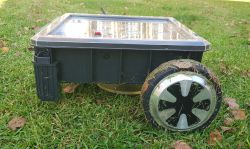
Device in operation. .
The idea to build one came from the desire to automate the mowing process, with the expertly advised mowers that would cope with this particular terrain coming out rather expensive due to the difficulties in the shape of the terrain. The second objective is to (at least presumably) save money (it will come out cheaper) and, above all, to have the fun of the construction as an added value. The design consists of as many modules as possible that are commonly available off-the-shelf (chassis, wheels/motors, motor controllers, cutting system, battery and its charging system, etc.), the only exception being a dedicated overall controller.
Basic description of the construction.
The running gear is built on 3 wheels, two drive wheels from a scooter once bought for a penny, they have a built-in drive system (bldc motor with Hall sensors), their advantages are high torque, simple adaptation to any structure and resistance by design to dirt. The third wheel is a furniture free-turning 360° wheel. The cutting system is the original motor from the Worx stand-alone mower, a custom cutting disc together with 3 knives from the Landroid mower (enlarged slightly than the original to increase the cutting diameter). Macalister brand housing or toolbox
Electronics.
All 3 motors (wheels and cutting disc) driven by reasonably cheap and popular Chinese bldc+Hall controllers, revs controlled by voltage from digital potentiometers. Current control of all motors on off-the-shelf Acs712 modules, battery charging module on universal CC/CV module, charging current control on ACS712. Wheel rotation control taken from Hall sensor pulses.
The boundary wire code receiver is an implementation of the circuit from Google patent US8392044 with minor modifications. A little more about the boundary wire later in the description.
The main controller is a dedicated board with a pic32mx470. The board contains the necessary digital and analogue IOs for ADC measurements (acs712) and digital signals from the other sensors, digital potentiometers for setting voltages to the drive systems, MRF24G Wi-Fi module for monitoring, remote updates etc., GPS module for coarse control of the boundary of the set area.
Mcu driven by a custom OS using the tcpip MLA stack and custom drivers for the necessary peripherals. In addition, the OS has a LOGO-like control pseudo-code interpreter (forward 10, right turn 90, etc.) together with event handling (of the type "boundary wire detected", etc.). This allows faster development of the driving algorithm at the test stage without the need to constantly flash the mcu. The code is uploaded via the built-in http server.
The boundary wire generator is based on pic10f222.
Battery pack is a custom 4S pack built from cell lion LG (bought for pennies) 10FX 10Ah + BMS.
Boundary wire concept. Boundary wire.
Conduit (or wire) boundary by transmitting the appropriate signal creates a virtual fence within which the mower is to move. This secures the boundaries of the lawn, flowerbeds, islands, etc. and even in some cases the wire can serve as a leading wire to the base/charging station. It is also worth mentioning that there are 'wireless' solutions based on GPS assisted with additional local correction to increase the precision of the position. As this solution requires additional equipment and is not very commonly used in commercial mowers (except for a few such as Ambrogio), I decided to base my own solution on a classic, proven wire.
In the first concept I tested a simple signal transmitter (30kHz) with its receiver. The circuit was a realisation suggested on some tutorial on the web on how to build a transmitter-receiver circuit for such a cable. Unfortunately, during quite intensive testing, this type of solution showed its rather significant drawbacks:
- the difficulty of accurately determining the distance to the wire. The wire is detected e.g. 20cm in front of it and another 20cm behind. Theoretically, one could
combine with sensitivity or transmit power to detect the moment of crossing more precisely, but this leads to another disadvantage:
- A rather significant dependence of the signal on weather conditions, the moisture in the soil just after rain changes the signal propagation conditions strongly. What tunes up in the "dry" will diverge in the wet
- the trouble of getting the cable to the islands in the middle of the lawn in such a way that it is not detectable by the lawnmower. It would need to be buried deep, plus possibly twisted together with the return wire to degrade the signal
The above disadvantages disqualified this type of solution altogether. It was necessary to resort to another concept, a little more complicated, which not only does not have the disadvantages of the previous one, but also, thanks to the physics of the phenomenon used, solves the problem of bringing the cables to the islands. The solution is probably used in all mowers of this type. It is based roughly on the detection of a special code transmitted by the wire and checking whether the received signal is in accordance with the expected pattern or reversed. Practically, this is realised in the simplest way by transmitting a signal modulated by so-called Manchester coding: the transmitter of the wire generates, for example, a 16-bit code, which the mower knows. The position of the receiving coil along the plane of the wire (in front or behind) determines the direction of the field lines generated by the wire and the direction of the currents generated in the receiving coil. And this, in turn, in Manchester coding determines whether the received code will follow the expected pattern or be inverted (i.e. all bits switched 1->0 0->1). This determines the position of whether the cutter is 'inside' the loop region created by the wire or 'outside'. At the same time, the code reversal is very sharp and occurs just after passing the wire. A strong transmit signal is not a problem, it is just that you know beforehand that you are approaching the wire but until the signal reverses the wire has not been passed. For details of the implementation of the solution, I refer you to Google Patent No. US8392044 where everything is described in detail along with a diagram of the receiver.
Getting the signal to the islands inside the mowing area is no longer a problem, simply lay the 'feed' wire to the island and the return wire close together in parallel (forming an omega shape), they do not need to be buried deeper. Cables laid close together in parallel only create an "inside" area signal, which will be ignored by the mower.. It is only when the wires are pulled apart by a minimum of 4-5cm that a detectable 'outer' area is created.
Other sensors to assist with mower movement.
In addition to detecting the permanent boundaries of the lawn, it would also be useful to detect unexpected obstacles. Trees, some left object in the path of the mower, resting animals etc. Originally, the main such sensor was to be an ultrasonic rangefinder. Unfortunately, the most popular cheap Chinese HC-SR04 module (its clone) turned out to be faulty, in an open area it generates a false reflection every now and then as if there was an obstacle close by. After googling it turned out to be some kind of flaw in the firmware of these sensors and most labelled as hc-SR04 have it. I bought a slightly more expensive, more branded one that doesn't have this flaw but doesn't really work in the field. Placed 10-15cm above the ground (max height is limited by the housing) it unfortunately sometimes returns the echo of a close obstacle. I suspect an uneven grass pattern causes such echoes. I have tried to solve the problem by using more advanced readout statistics to reject false positives. However, still very narrow obstacles (a thin tree, a spade left stuck in) will be invisible to such a sensor. In tests, we have found that a fairly effective obstacle sensor is the control of the current drawn by the wheels. This is currently the main method of obstacle detection and is performing satisfactorily so far.
Of course, if anyone here has a proven ultrasonic or IR sun-proof sensor to suggest, I would be happy to test it. Another interesting obstacle detection solution is, for example, a peripheral hose with a pressure sensor. A collision with an obstacle presses on the hose, in which the pressure measured by this sensor increases.
Motor driving the cutting disc.
I decided to use an off-the-shelf solution here, there was no point in combining with a custom drive when off-the-shelf ones are affordable. The choice was between two motors: with or without hall. I had previously tested one without Hall, unfortunately the nature of controlling such a motor is a bit rough. The controller at start-up is a bit hesitant, having to jerk the motor to realise the shaft position (back EMF). In addition, there is some difficulty in stability at low revs under load (audible commutation "knocks"). And in this case the cutting disc does not need to rotate quickly. Since my previous experience with Hall motors suggested that such a one is more precisely controlled in the slow rpm ranges I decided to go for one with Hall. The motor of choice was from a Worx mower model 50032554.
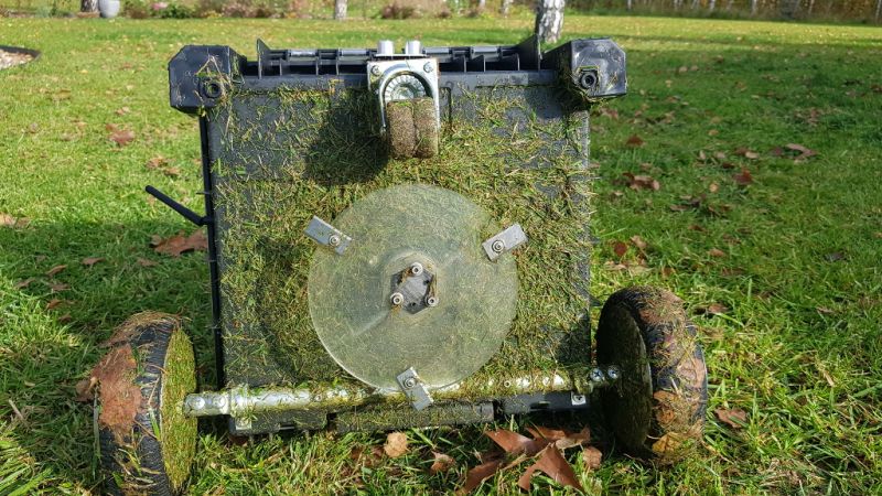
Cutting disc. .
 .
.
The original cutting disc for this engine is a little small and I'm keen to mow wider, at least 20cm (the original is 14cm, I think). The engine has plenty of power, so I can easily handle a larger one. The disc is CNC-cut from polycarbonate, with 3 cutting blades bolted to it every 120stp. Cutting height adjustment is achieved by selecting a suitable extension between the disc and the mounting bracket on the motor axis (3D printed component). Cutting height is adjusted very rarely, in fact only once, so unscrewing the 3 screws holding the extension piece and the disc is not a problem..
Algorithm of mowing.
Most low-cost mowers drive randomly, bouncing off boundary wires or obstacles, changing the angle of the bounce to avoid the effect of being driven into a corner. Then the mower may loop around a certain closed section repeating it indefinitely. Some additionally detect local density of grass and can make an extra circle in such a place.Since such a mower drives practically non-stop during the season, there is a high probability that practically every place will be visited by the mower in no more than a noticeable increment, i.e. a few days. In my case, the terrain is quite complex, with islands, connectors etc. so I have divided it into 3 areas. Driving all over would be inefficient. It is better to focus more often on one because you can finish it faster and then move on to the next one. The whole thing should be completed in a maximum of 3 days. To roughly delineate these area boundaries, the mower uses GPS.
What is still to be done.
Shield shield. Charging station. Algorithm for station search, support with additional lead wire to station, docking. No concept of charging contacts withstanding currents up to 5A as yet. Would love to hear ideas on how to do this.
Problems that have come up during testing so far.
Phantom wire detections where there is none. It turns out that the spinning knives generate Manchester decoder-detectable pulses that every now and then randomly match the 16-bit pattern (we only have 65tys of combinations) i.e. its mirror image. This is not a significant problem (the mower just changes direction). I plan to change the transmit frequency to not coincide with the rotation of the disc and possibly change the code to 32bit which will definitely reduce the likelihood of random generation by interference of this type.
A free steering wheel with an exposed steering bearing is not a good idea, I'm worried about it seizing up quickly with cuttings. This is where adding a planned cutting disc guard or replacing it with a wheel with a shielded bearing might help.
Cool? Ranking DIY


