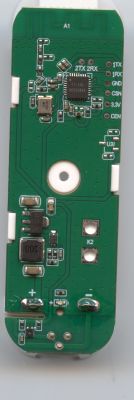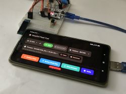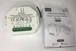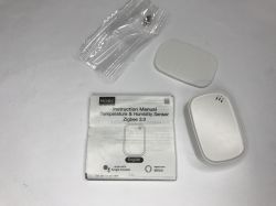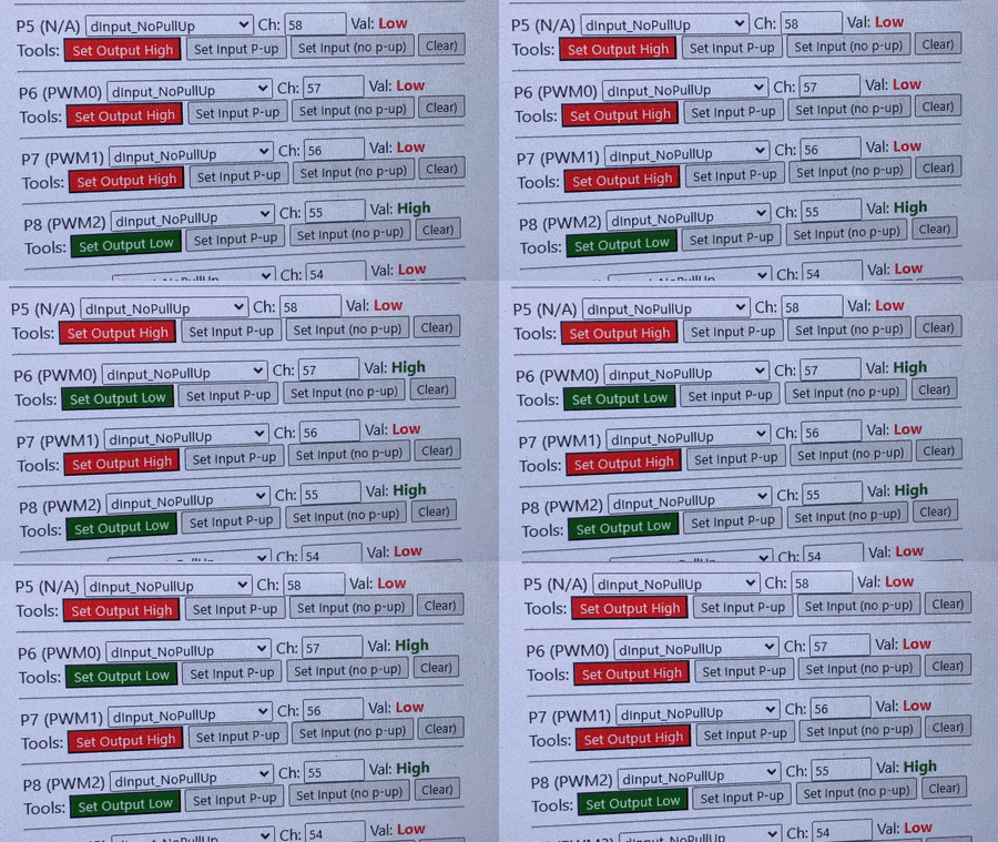
Changing the firmware of an IoT device usually takes place in two steps: first, a new batch must be uploaded (usually via UART), and then the new firmware must be properly configured to work with our equipment. This configuration includes assigning the role to selected GPIOs, i.e. determining on which pin there is, for example, a relay, on which there is a button, and on which there is, for example, an LED indicating the WiFi status.
This search for GPIO roles is rather familiar to all users of firmware such as Tasmota, or even mine OpenBeken , there are different ways to set GPIO roles, including:
- you can use a ready-made template already created by someone before, there are templates for OBK here
- you can extract the configuration from the Tuya batch, which has been supported recently BK7231GUIFlashTool but more on that another time
- you can test the board with a multimeter and visually, check where which pin is connected, of course after disconnecting it from the power supply, also bearing in mind that some peripherals are connected through resistors and so on
- you can also guess.
Here I will deal with ... the topic of guessing, more specifically, a tool that makes this guesswork easier. But first - a little reminder.
The BK7231 chips, as well as other supported platforms (W600, W800, BL602, XR809), have roughly 30 available GPIOs. As a rule, only some of these pins are used, even though an IoT device may have several relays and several buttons. This means you have to somehow figure out which pin has what role...
Both in Tasmot and OBK, buttons and relays are combined into groups, giving them indexes. At OpenBeken, these are the so-called channels. Button and relay on one channel work together. Similarly, instead of the (momentary) button, you can use the TglChannelOnToggle role (to change the state of the relay when someone switches the bistable switch) or e.g. dInput (to rewrite the 1:1 state from the input to the relay, or dInput_n, i.e. with negation).
Similarly with PWM - for PWM pins, you can (or even need to) set channels, sequentially with indexes 1, 2, 3, 4 and 5, to determine which PWM is responsible for red, which for green, etc. The order is of course RGBCW.
Details in the documentation:
https://github.com/openshwprojects/OpenBK7231T_App/blob/main/docs/README.md
Here is a list of available GPIO roles:
https://github.com/openshwprojects/OpenBK7231T_App/blob/main/docs/ioRoles.md
It is also worth looking at the list of devices inside:
https://openbekeniot.github.io/webapp/devicesList.html
The topic assumes a basic knowledge of these concepts.
GPIO Doctor at OpenBeken
The tool for convenient pin testing in OpenBeken resides in the so-called Web App, i.e. in the Web Application, which is an overlay on the device with this batch. This application is characterized by the way it is createdand loading - it is written entirely in Javascript/HTML/Vue, and is loaded from Github, via GH Pages. This has several consequences:
- this application takes practically no load on the IoT device (only the REST interface, quite modest, through which it communicates) takes up space
- this application can be freely developed with dozens of convenient tools, practically zero cost of memory on BK or other system
- this application requires a network connection, but you can also host it locally everything is open source
- this application can refresh itself conveniently in the background via Ajax and gives a greater level of interaction than classic websites
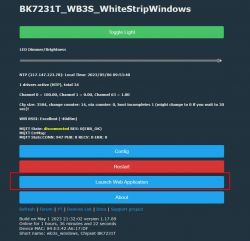
We enable the application in OBK, Web Application button , then select a tab GPIO Doctor to open said Doctor.
This is what GPIO Doctor looks like:
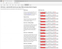
Before using it, remember that the changes are automatically saved there, so if we already have a configuration, it may be worth exporting it in the Config tab.
Using GPIODoctor to search for relays/LEDs :
One by one, for each pin, press the "Set output high" button and after a while, when this button changes to "Set output low", press it again. We look/listen to see if the given relay/LED reacts. If so - we found the pin responsible for this LED. If not, you can click "Clear" to clear the role of the pin and search further.
Using GPIODoctor to search for door buttons/sensors :
One by one, for each pin, first press Set input pullup, and then physically press the button of interest and hold it. We observe whether the state on a given pin has changed. The status will refresh itself, on its own, in the background. This does not require a page reload. Just remember to hold the button, not click it. You have to hold for a second and see if there is another state.
If the input pullup doesn't work (it is used by default for buttons by Tuya, and for example we are looking for a door sensor, you can try the second input mode - without pullup).
Below is a video of the tests of the door opening sensor, you can see how the status refreshes:
(in the video above I do not move anything on the computer, I only move the door opening sensor, the website refreshes itself in the background)
If we do not find anything on a given pin, we clear it (you can also set all of them to input mode and test them at once), when we find it, we can change the pin mode to Button (default testing is done on dInput, i.e. digital input, digital entry).
Using GPIODoctor to search for PWM LEDs :
All RGB, RGBCW products are usually based on PWM pins. We search for PWM pins in the output mode, i.e. just like relays, everything as discussed earlier, then it's only worth changing the role to PWM manually and setting the channel (R is 1, G is 2, B is 3, C is 4, W is 5, red - red, green - green, blue - blue, cool white - cold white, warm white - warm white).
What does GPIODoctor not support?
Of the more popular mechanisms, GPIODoctor does not support two things:
- "I2C" or "I2C style" controllers for LEDs, type SM2135, SM2235, BP5758, etc.
- devices based on TuyaMCU, in their case it is worth getting acquainted with analyzer
What after finding the pins?
After configuring everything, it is worth clearing the unused pins/channels with the Clear button, as well as exporting the template in the Config tab, so that you have a backup copy for the future. It may also be necessary, for example, to change the channel, e.g. when we are looking for buttons, we are looking for the dInput pin in the role mode (digital input), but if we already find a button and we want it to work as a button, then we need to set the role of Button manually. The same with the channel - you have to manually set the same channel on the button that has the relay. It's to connect them together. This should be remembered, otherwise the firmware will not know which button operates which relay.
What if not GPIODoctor?
It is worth mentioning that the latest version of the flasher can be found here:
https://github.com/openshwprojects/BK7231GUIFlashTool
allows you to simply drag and drop a 2MB Tuya input to the decoder field:
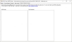
and get the pinout/JSON to paste into Web App:
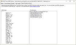
Unfortunately, this doesn't always work - e.g. for the deep sleep door sensor, the Tuya JSON configuration could not be found.
Summary
GPIODoctor has already helped me to run several devices for one reader (he sent me some products to upload OBK - then the products are of course sent back, I will present them soon). It is certainly more convenient than manually changing the role of pins and returning to the main panel to check if a given relay is working. And it's certainly easier than a similar process in Tasmot, where after changing the GPIO role, the device had to reboot for some strange reason. I actually spent too much time on these devices with Tasmota. Now at least in OBK it will be a bit faster...
The use of GPIO Doctor may require updating the firmware to the version from today/yesterday (i.e. May 5, 2023).
If there are any problems with the tool, or suggestions on how to improve it - please write boldly, I will be happy to help.
Cool? Ranking DIY Helpful post? Buy me a coffee.


