logo elektroda
logo elektroda
X
logo elektroda

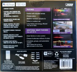
Feit Electric "Smart Color Chasing Strip Light" w/BK7231N and SM16703 SM16704

darconeous 5322 30
ADVERTISEMENT
  • #1 20791392
    darconeous
    Level 3  
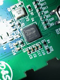
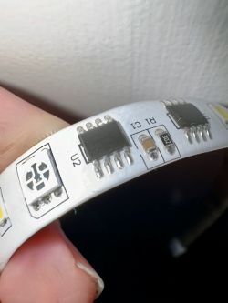
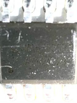
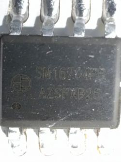
    Howdy. I just picked up a Feit Electric 20-ft LED chaser strip and promptly tore it down. Seemed to be using a BK7231N. The strip is RGBCW, but it is a little strange in that each segment has two chips: a SM16703 and a SM16704. This means there are, ua... 7 channels per segment, but I only see 5 being used. I haven't tried driving it yet, so I'm not sure what the channel order is yet.

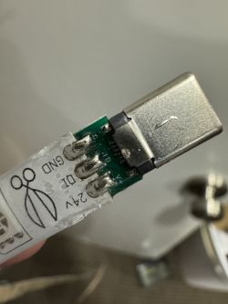
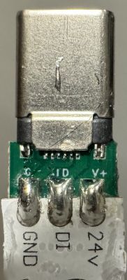
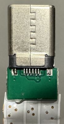
    Bizarrely, the connector for the LED strip is the same as USB-C, even though it is very clearly NOT USB-C. They are only sending three signals over it: +24v, DOUT, and GND. I'm not yet sure how they are mapping those to the USB-C pins yet, so not sure if it would fry anything if someone decided to try to connect it to their computer. Very strange decision.

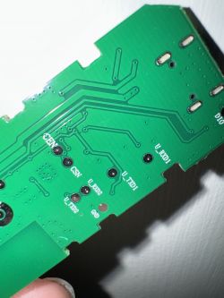
    In any case, I haven't tried changing the firmware yet, but it looks like all the important pins have nicely labeled test points.

    It was something like $25 at Costco.

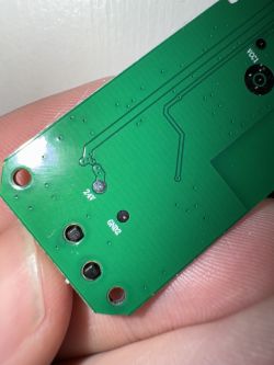
    Feit Electric smart LED strip packaging. Feit Electric LED strip packaging with features. Close-up of a circuit board with various electronic components and a USB-C connector. Close-up of an LED connector with a USB-C-like end. LED strip connector resembling USB-C with three pins labeled G, ID, V+. LED connector resembling USB-C on a green PCB. Close-up of a BK7231N chip on a printed circuit board. PCB of Feit Electric LED strip with SM16703 and SM16704 chips visible. Close-up of SM16703 chip with AZYVA23 text on its surface. Close-up view of the SM16704PE chip with markings AZSFAB25. Close-up of a green circuit board with visible traces and pin labels. Close-up of a green circuit board with markings 24V and GND2 against a hand background.
  • ADVERTISEMENT
  • #2 20791759
    p.kaczmarek2
    Moderator Smart Home
    I think that we have a SM16703 , so maybe, just make a 2MB flash backup and give it a try? I can try to guide you step by step with that.
    Helpful post? Buy me a coffee.
  • ADVERTISEMENT
  • #3 20792424
    darconeous
    Level 3  

    Will do. Maybe the weekend before I can give it a shot. I had originally planned to just toss the controller and replace it with a PicoW, but seeing your firmware has made me reconsider.

    The SM16703 is the same as the SM16704, except with an extra channel. So I expect that the protocol should be the same except with 7 channels instead of 3 or 4.

    Maybe each segment can control two sets of W and C, but only one RGB? In that case, the channel order would be something like RGBWCWC, or RGBWWCC... I guess we will find out this weekend!

    Awesome work, by the way. Looking forward to digging into the details of your firmware.

    BTW: Is the BK7231N based on RISC-V? I kept trying to definitively hammer down the arch, but couldn't seem to find a decent datasheet.
  • #4 20803236
    darconeous
    Level 3  

    Ok, I managed to get it flashed using the python command line tool on my Mac. I can now access the web interface without too much trouble. I did back up what I could of the firmware, but I'm not sure if I was able to extract it properly because it kept having CRC errors.

    Now I'm at the point where I need to figure out what the GPIOs are for the button and the data line. I was hoping there was a command in the OpenBK firmware that would allow me to dump the existing state of the pins so that I could at least have a straightforward path to identifying the button.

    Any suggestions or tips/tricks for how best to identify the right pins?

    Added after 18 [minutes]:

    Ah, I managed to find the GPIO finder. Pin 24 is the button. Will go looking for the other pins soon. I think there is a MOSFET for determining if power should go to the strip or not, as well as the actual data pin.
  • ADVERTISEMENT
  • #5 20803289
    p.kaczmarek2
    Moderator Smart Home
    Sorry for the late reply. If this device is using individually adressible LEDs, then data is always P16. This is because they are using SPI to push pixels with correct timings. Have you tried SM16703 driver?
    Helpful post? Buy me a coffee.
  • #6 20804661
    darconeous
    Level 3  
    Allright, here is the pinout:

    P16: DOUT (to DIN on the strip)
    P22: 24v Power Enable (Controls the +24v pin to the LED strip)
    P24: Button (low when pressed, high when not pressed)

    I've tried the SM16703 driver and it seems like there is a bit shift for some reason that causes the channels to not quite line up properly. But from what I can tell, the channel order is this:

    Channel 1: Red
    Channel 2: Green
    Channel 3: Blue
    Channel 4: Warm White 1
    Channel 5: Warm White 2 (Same LED as channel 4, but just additional brightness)
    Channel 6: Cool White 1
    Channel 7: Cool White 2 (Same LED as channel 6, but just additional brightness)

    So it seems like the RGB channels can go from 0-255, but the white channels can effectively go from 0-510.

    The SM16703 driver definitely seems buggy, even taking into account it is only intended for 3 channels instead of 7. It doesn't seem to clear out the buffer at initialization, so everything starts with random values unless you initialize them all explicitly. It also doesn't seem to prevent you from setting LED values that are larger than initialization, leading to some memory corruption that causes the device to get into a bad state. There also seems to be an odd bit-shift problem that I'm seeing where the channels don't quite line up bit-for-bit, so setting one channel to 255 seems to cause some of those bits to be set on the previous channel. Not sure why this is the case.

    But I can control the lights at least!

    For a generic driver I think you would want to have the following configuration options:

    1. Number of channels.
    2. Channel mapping. (RGB, BGR, WWRGBCC, etc)
    3. Maybe timing information so that it could also be compatible with neopixels?

    UPDATE: I haven't tested this yet, but I think the sort of changes we would want for the driver look something like this:

    
    diff --git a/src/driver/drv_sm16703P.c b/src/driver/drv_sm16703P.c
    index e0e011ce..0593dbd6 100644
    --- a/src/driver/drv_sm16703P.c
    +++ b/src/driver/drv_sm16703P.c
    @@ -22,12 +22,16 @@
     
     #include "drv_spidma.h"
     
    +#define SM16703P_MAX_CHANNELS		(8)
    +
     static uint8_t data_translate[4] = {0b10001000, 0b10001110, 0b11101000, 0b11101110};
     
    -UINT8 *send_buf;
    -struct spi_message *spi_msg;
    +UINT8 *send_buf = NULL;
    +struct spi_message *spi_msg = NULL;
     BOOLEAN initialized = false;
     uint32_t pixel_count = 0;
    +uint8_t channel_count = 3;
    +uint8_t channel_map[SM16703P_MAX_CHANNELS];
     
     static uint8_t translate_2bit(uint8_t input) {
     	//ADDLOG_INFO(LOG_FEATURE_CMD, "Translate 0x%02x to 0x%02x", (input & 0b00000011), data_translate[(input & 0b00000011)]);
    @@ -58,7 +62,7 @@ static void SM16703P_setMultiplePixel(uint32_t pixel, UINT8 *data) {
     
     	// Iterate over pixel
     	uint8_t *dst = spi_msg->send_buf + 2;
    -	for (uint32_t i = 0; i < pixel * 3; i++) {
    +	for (uint32_t i = 0; i < pixel * channel_count; i++) {
     		uint8_t input = *data++;
     		*dst++ = translate_2bit((input >> 6));
     		*dst++ = translate_2bit((input >> 4));
    @@ -66,14 +70,21 @@ static void SM16703P_setMultiplePixel(uint32_t pixel, UINT8 *data) {
     		*dst++ = translate_2bit(input);
     	}
     }
    -void SM16703P_setPixel(int pixel, int r, int g, int b) {
    -	translate_byte(r, spi_msg->send_buf + (2 + 0 + (pixel * 3 * 4)));
    -	translate_byte(g, spi_msg->send_buf + (2 + 4 + (pixel * 3 * 4)));
    -	translate_byte(b, spi_msg->send_buf + (2 + 8 + (pixel * 3 * 4)));
    +void SM16703P_setPixel(int pixel, int r, int g, int b, int w, int c) {
    +	translate_byte(r, spi_msg->send_buf + (2 + channel_map[0]*4 + (pixel * channel_count * 4)));
    +	translate_byte(g, spi_msg->send_buf + (2 + channel_map[1]*4 + (pixel * channel_count * 4)));
    +	translate_byte(b, spi_msg->send_buf + (2 + channel_map[2]*4 + (pixel * channel_count * 4)));
    +
    +	if (channel_count >= 4) {
    +		translate_byte(w, spi_msg->send_buf + (2 + channel_map[3]*4 + (pixel * channel_count * 4)));
    +	}
    +	if (channel_count >= 5) {
    +		translate_byte(c, spi_msg->send_buf + (2 + channel_map[4]*4 + (pixel * channel_count * 4)));
    +	}
     }
     
     commandResult_t SM16703P_CMD_setPixel(const void *context, const char *cmd, const char *args, int flags) {
    -	int pixel, i, r, g, b;
    +	int pixel, i, r, g, b, w, c;
     	Tokenizer_TokenizeString(args, 0);
     
     	if (Tokenizer_GetArgsCount() != 4) {
    @@ -86,32 +97,43 @@ commandResult_t SM16703P_CMD_setPixel(const void *context, const char *cmd, cons
     	g = Tokenizer_GetArgIntegerRange(2, 0, 255);
     	b = Tokenizer_GetArgIntegerRange(3, 0, 255);
     
    -	ADDLOG_INFO(LOG_FEATURE_CMD, "Set Pixel %i to R %i G %i B %i", pixel, r, g, b);
    +	if (channel_count >= 4) {
    +		w = Tokenizer_GetArgIntegerRange(4, 0, 255);
    +	}
    +
    +	if (channel_count >= 5) {
    +		c = Tokenizer_GetArgIntegerRange(5, 0, 255);
    +	}
    +
    +	if (channel_count <= 3) {
    +		ADDLOG_INFO(LOG_FEATURE_CMD, "Set Pixel %i to R %i G %i B %i", pixel, r, g, b);
    +	} else if (channel_count <= 4) {
    +		ADDLOG_INFO(LOG_FEATURE_CMD, "Set Pixel %i to R %i G %i B %i W %i", pixel, r, g, b, w);
    +	} else {
    +		ADDLOG_INFO(LOG_FEATURE_CMD, "Set Pixel %i to R %i G %i B %i W %i C %i", pixel, r, g, b, w, c);
    +	}
     
     	if (pixel < 0) {
     		for (i = 0; i < pixel_count; i++) {
    -			SM16703P_setPixel(i, r, g, b);
    +			SM16703P_setPixel(i, r, g, b, w, c);
     		}
     	}
    -	else {
    -		SM16703P_setPixel(pixel, r, g, b);
    -
    -		ADDLOG_INFO(LOG_FEATURE_CMD, "Raw Data 0x%02x 0x%02x 0x%02x 0x%02x - 0x%02x 0x%02x 0x%02x 0x%02x - 0x%02x 0x%02x 0x%02x 0x%02x",
    -			spi_msg->send_buf[2 + 0 + (pixel * 3 * 4)],
    -			spi_msg->send_buf[2 + 1 + (pixel * 3 * 4)],
    -			spi_msg->send_buf[2 + 2 + (pixel * 3 * 4)],
    -			spi_msg->send_buf[2 + 3 + (pixel * 3 * 4)],
    -			spi_msg->send_buf[2 + 4 + (pixel * 3 * 4)],
    -			spi_msg->send_buf[2 + 5 + (pixel * 3 * 4)],
    -			spi_msg->send_buf[2 + 6 + (pixel * 3 * 4)],
    -			spi_msg->send_buf[2 + 7 + (pixel * 3 * 4)],
    -			spi_msg->send_buf[2 + 8 + (pixel * 3 * 4)],
    -			spi_msg->send_buf[2 + 9 + (pixel * 3 * 4)],
    -			spi_msg->send_buf[2 + 10 + (pixel * 3 * 4)],
    -			spi_msg->send_buf[2 + 11 + (pixel * 3 * 4)]);
    +	else if (pixel < pixel_count) {
    +		SM16703P_setPixel(pixel, r, g, b, w, c);
    +
    +		for (i = 0; i < channel_count; i++) {
    +			ADDLOG_INFO(LOG_FEATURE_CMD, "Raw Data CH%i 0x%02x 0x%02x 0x%02x 0x%02x",
    +				i,
    +				spi_msg->send_buf[2 + 0 + i*4 + (pixel * channel_count * 4)],
    +				spi_msg->send_buf[2 + 1 + i*4 + (pixel * channel_count * 4)],
    +				spi_msg->send_buf[2 + 2 + i*4 + (pixel * channel_count * 4)],
    +				spi_msg->send_buf[2 + 3 + i*4 + (pixel * channel_count * 4)]);
    +		}
    +	} else {
    +		ADDLOG_INFO(LOG_FEATURE_CMD, "Bad pixel index %i", pixel);
    +		return CMD_RES_BAD_ARGUMENT;
     	}
     
    -
     	return CMD_RES_OK;
     }
     
    @@ -120,30 +142,64 @@ static void SM16703P_Send(byte *data, int dataSize) {
     }
     
     commandResult_t SM16703P_Start(const void *context, const char *cmd, const char *args, int flags) {
    -
    +	int i;
     	Tokenizer_TokenizeString(args, 0);
     
     	if (Tokenizer_GetArgsCount() == 0) {
    -		ADDLOG_INFO(LOG_FEATURE_CMD, "Not Enough Arguments for init SM16703P: Amount of LEDs missing");
    +		ADDLOG_INFO(LOG_FEATURE_CMD, "Not Enough Arguments for init SM16703P: Pixel count is missing");
     		return CMD_RES_NOT_ENOUGH_ARGUMENTS;
     	}
     
     	pixel_count = Tokenizer_GetArgIntegerRange(0, 0, 255);
     
    +	if (Tokenizer_GetArgsCount() >= 2) {
    +		channel_count = Tokenizer_GetArgIntegerRange(1, 0, SM16703P_MAX_CHANNELS);
    +	} else {
    +		channel_count = 3;
    +	}
    +
    +	if (Tokenizer_GetArgsCount() >= 3) {
    +		for (i = 0; i < channel_count; i++) {
    +			channel_map[i] = Tokenizer_GetArgIntegerRange(2+i, 0, 8);
    +			if (channel_map[i] >= channel_count) {
    +				ADDLOG_INFO(LOG_FEATURE_CMD, "Bad channel index %i for channel %i", channel_map[i], i);
    +				return CMD_RES_BAD_ARGUMENT;
    +			}
    +		}
    +	} else {
    +		for (i = 0; i < channel_count; i++) {
    +			channel_map[i] = i;
    +		}
    +	}
    +
     	ADDLOG_INFO(LOG_FEATURE_CMD, "Register driver with %i LEDs", pixel_count);
     
    +	// Free the old buffer if one was allocated.
    +	if (initialized) {
    +		os_free(send_buf);
    +	}
    +
     	// Prepare buffer
    -	uint32_t buffer_size = 2 + (pixel_count * 3 * 4);			  //Add two bytes for "Reset"
    +	uint32_t buffer_size = 2 + (pixel_count * channel_count * 4);			  //Add two bytes for "Reset"
     	send_buf = (UINT8 *)os_malloc(sizeof(UINT8) * (buffer_size)); //18LEDs x RGB x 4Bytes
    -	int i;
     
     	send_buf[0] = 0;
     	send_buf[1] = 0;
     
    +	// Turn on all channels on all pixels at maximum brightness.
    +	// TODO: Is this REALLY what we want to do? Shouldn't we be
    +	//       be setting the initial value to be encoded zero bits
    +	//       instead of encoded 1 bits? Consider changing to
    +	//       0b10001000 after discussion.
     	for (i = 2; i < buffer_size; i++) {
     		send_buf[i] = 0b11101110;
     	}
     
    +	// Free the old buffer if one was allocated.
    +	if (initialized) {
    +		os_free(spi_msg);
    +	}
    +
     	spi_msg = os_malloc(sizeof(struct spi_message));
     	spi_msg->send_buf = send_buf;
     	spi_msg->send_len = buffer_size;


    This would allow you to initialize with a custom number of channels like this (7 channels, RGBWxCx)

    
    SM16703P_Init 10 7 0 1 2 3 5


    But if you don't specify the number of channels it assumes "3 0 1 2" (3 channels, RGB order).

    Again, I haven't tested the above code (not even sure if it compiles yet) but it should be a good start.

    Added after 11 [hours] 22 [minutes]:

    Argh... There seems something very strange with the SPI driver. I keep getting very strange offset/looping behavior on the SPI output, things like the channels being off by two or so, but still actually wrapping around in such a way that if you fill all of the pixels that all the pixels still get lit. The offset seems to change depending on the size of the buffer.

    My brain hurts too much to continue working on this tonight.


    UPDATE:

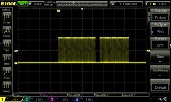
    Yeah, the SPI output isn't matching up with the data in the buffer:

    Oscilloscope screen showing SPI DMA test signal.

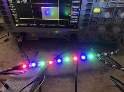
    You can see that gap in the middle: That's the "reset" pulse (extended to 7 bytes in my code) that is supposed to be at the start of the transmission. In other words, the whole transmission should just appear as a big block, not two blocks. For some reason, the "reset" pulse is in the middle!

    If I reduce the total number of lights to 2 (7 channels each) then I can reliably get the reset pulse at the start. I'm really confused why the SPI output isn't lined up with the order in memory. Any ideas?
  • #7 20807690
    darconeous
    Level 3  
    Well, out of frustration with the SPI DMA stuff, I tried to bitbang out the bits... But the shortest pulse I could muster was 2µs—way longer than the 0.3µs required. I might be able to improve that timing significantly by banging on the GPIO registers directly, which is the approach that the bitstream bit-banging method from Micropython does, and it manages to pull it off with the RISC-V variant of the ESP32.

    Is there anything I should know about how to increase my bit-banging rate, or is there some sort of fundamental limit that I'm going to end up running into?
  • #8 20807800
    p.kaczmarek2
    Moderator Smart Home
    Sorry for the late reply, @darconeous . To the best of my knowledge, it is not possible to do bit bang on this platform, due to the flash instructions cache system, which is practically random. I tried this approach and failed in the past. I tried even with nop operators. The only way for that to work would be to use a ramfunc, which is a function that resides in RAM and is executed directly from RAM, but again, I've found a problem with creating my own ramfunc as well...
    https://github.com/openshwprojects/OpenBK7231T_App/issues/497

    Are you really sure that you're doing everything ok with the SPI? I haven't tried it myself yet except few tests with WS2812B but it still seemed to kind work.... I need to take out my scope to check, or we can ask @DeDaMrAz to check this as well and show here the waveforms.
    Helpful post? Buy me a coffee.
  • #9 20808053
    DeDaMrAz
    Level 19  

    @darconeous

    Do you mind sharing the original FW dump?

    I found the same strip on eBay so I'll get that in a couple of weeks so we can test and support them fully.
  • #10 20808173
    p.kaczmarek2
    Moderator Smart Home
    @DeDaMrAz we could just flash his backup on our CB3S and do the scoping with original firmware then
    Helpful post? Buy me a coffee.
  • #11 20810671
    paulcarhuff
    Level 1  

    I just want to thank you for even just trying with these. I appreciate these lights for the price, but the programmability from Feit's app leaves a bit to be desired. (Even if just a little)

    I am sometime in the near future planning to do some Neopixel programming, but I'm a baby when it comes to coding at this point. I used to use VB and JScript a touch during school but that was 20+ years ago!

    ANYHOW...
    I'm hopeful that one day I'll be able to "per pixel" control these lights. A decent price for a strip, a controller, a power supply, and a mostly functional app in my humble opinion. Pretty close to almost all my wants in the app, but not quite 100%

    The hardware is there!

    Added after 31 [minutes]:

    Hey, IDK if this matters, but most of the scenes in the Feit app seem to assume two strips are connected together. It was driving me mad all night till I just figured it out. But where things should be symmetrical even accounting for that, they are not always. Like there's an offset... idk, but when I realized that I thought someone else might make use of it.

    Thanks again!
  • #12 20843831
    missoulapc
    Level 1  

    Any further luck? I picked up a few of these at Costco. Flashed without a problem. Just trying to nail down how to get some light out of them.
  • #13 20844769
    DeDaMrAz
    Level 19  

    @missoulapc

    We don't have that device at hand, so it is difficult to do anything about it right now. If somebody is willing to sell it and send it to us, we will gladly try to incorporate and support it.
  • #14 20851058
    CliffBraun
    Level 1  

    I have an extra one of these I could send somewhere if it would help.
  • #15 20851080
    p.kaczmarek2
    Moderator Smart Home
    Where are you from? Depending on location, shipping to Poland may be expensive. Send me a PM if you're interested in helping us.
    Helpful post? Buy me a coffee.
  • #16 20868940
    kevdel
    Level 4  

    >>20808053

    Did you get a copy of the FW? I have one from a unit I bought last weekend.
  • #19 20869547
    kevdel
    Level 4  

    >>20868971

    If you ever need a homework to test on, then I'm happy to use mine to load dev solutions.
  • #20 20869549
    DeDaMrAz
    Level 19  
    kevdel wrote:
    >>20868971

    if you ever need a hw to test on then I'm happy to use mine to load dev solutions.


    Thank you for commitment unfortunately we have to do tests locally so we can provide a solution. We appreciated greatly the backup you provided we are going to work with it and provide updates here.


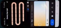
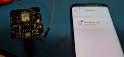
    View of a smartphone app screen displaying LED lighting settings Chasing Tape Light. Microcontroller connected to a mobile device with an app screen showing device pairing.

    P24 is the switch on the device, used for pairing.

    @p.kaczmarek2 we should probably use our modified modules for testing, right?

    Thank you.
  • #21 20869629
    p.kaczmarek2
    Moderator Smart Home
    P16 is a SPI output used for pixels data, we have modified modules for that:
    How to access hardware SPI port on CB2S? P16 (MOSI) GPIO breakout method
    It is not available on unmodified CB2S and not on CB3S. You need either the modification from link above or CBU for that
    Helpful post? Buy me a coffee.
  • #23 20890614
    kevdel
    Level 4  
    By chance @DeDaMrAz , any update on the investigation? If there is anything I can do to help, then please let me know! Thanks!
  • #24 20931119
    Sarain
    Level 4  

    I've been following this thread with interest and I'm also curious if there are any updates on support.

    In the hope that these will eventually be supported, I took a small risk in buying a couple of these around Christmas time.

    I know this is volunteer work, so totally understand if it's not ready yet. Just wanted to check, since there haven't been any status updates in a while.

    Best Regards!
  • #25 20937193
    p.kaczmarek2
    Moderator Smart Home
    darconeous wrote:

    UPDATE:

    Yeah, the SPI output isn't matching up with the data in the buffer:

    Oscilloscope screen showing SPI DMA test signal.

    You can see that gap in the middle: That's the "reset" pulse (extended to 7 bytes in my code) that is supposed to be at the start of the transmission. In other words, the whole transmission should just appear as a big block, not two blocks. For some reason, the "reset" pulse is in the middle!

    If I reduce the total number of lights to 2 (7 channels each) then I can reliably get the reset pulse at the start. I'm really confused why the SPI output isn't lined up with the order in memory. Any ideas?

    I can only confirm that I've spent a day testing the SPI DMA and I arrived at the same conclusion.

    There is some strange instability that causes a random lag in transfer.

    I have tried to fix it, by, for example, doing a NOP loop until SPI DMA send everything, but it still happens.

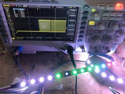
    See WS2812B test below, correct display:
    WS2812B LED strip connected to an oscilloscope, showing display irregularity.
    Randomly, SPI DMA display is broken:
    Rigol DS1054Z oscilloscope displaying a signal and a WS2812B LED strip.
    I do not know currently what causes this issue. We need more information, any help is wanted.
    Helpful post? Buy me a coffee.
  • ADVERTISEMENT
  • #26 20966214
    p.kaczmarek2
    Moderator Smart Home
    The SPI DMA driver bug has been fixed. The SM16703P/WS2812B/etc LEDs should work good now. Please update your devices. For scripting configuration, please see:
    OpenBeken WS2812B driver (compatible with SM16703P, etc) - short scripting presentation
    We can continue discussion there. The more advanced animation will be added soon, stay tuned!
    Helpful post? Buy me a coffee.
  • #27 21315554
    sasipraveen39
    Level 1  
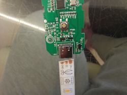
    I have the same LED lights from Costco and have a lot of cut excess strips that I'm trying to solder together to form one long strip light. I'm attempting to solder the strip light directly to the controller. Does anyone know which pins on the USB-C SMD connector on the controller correspond to GND, 24V, and Dout? Thanks in advance.

    Close-up of a circuit board with a USB-C port and a LED strip labeled GND, 24V, and Dout.
  • #28 21315812
    p.kaczmarek2
    Moderator Smart Home
    Do you have a multimeter? It should be very easy to check.
    Dout is P16, hardware SPI output.
    Please check this topic to see where P16 on QFN case is:
    BK7231 datasheet, pinout, programming, specification, wiki (BK7231T, BK7231N)
    Keep in mind that first pin is marked by a dot. Futhermore, you may double check it by looking at crystal oscillator pins.
    Helpful post? Buy me a coffee.
  • #29 21539283
    Sarain
    Level 4  
    I realize this thread is rather old but this seems to be the main one for discussing this particular Feit Electric branded LED strip. Happy to start a new thread for this if that would be better.

    Thanks to everyone involved in getting the SM16703 driver working on the BK7231N!
    I'm finally getting back to trying this out with a new OpenBK release (1.18.94) on these LED strips. I have things set up and mostly working in the sense that I can use a series of SM16703P_SetPixel commands to predictably control which LEDs come on.

    The problem I'm still having is that this strip uses both the SM16703 and SM16704, so 7 channels per segment, in a R G B WW WW CW CW pattern. The normal SM16703P_SetPixel command expects 3 channels (for RGB).

    So, I can run the following to set the first two segments to full Green (as an example):
    SM16703P_Init 4
    SM16703P_SetPixel 0 0 255 0
    SM16703P_SetPixel 1 0 0 0
    SM16703P_SetPixel 2 0 0 255
    SM16703P_SetPixel 3 0 0 0
    SM16703P_Start


    This is kind of annoying though, since the odd number of channels makes it hard to keep track of the position of each color at arbitrary points within the strip.

    Looks like @darconeous did some work towards supporting an arbitrary number of channels and channel mapping in drv_sm16703P.c from his post above. This isn't in the main repo builds though. For anyone still using these strips, have you found a good/better way to control them? If merging @darconeous changes into the latest version and building it myself is the answer, I can go that route. If there's a simpler route (or plans to support something similar), I can wait and/or potentially help out too.

    My ultimate goal is to use the new PixelAnim driver to animate this strip and control it from Home Assistant.
  • #30 21540498
    p.kaczmarek2
    Moderator Smart Home
    I would also like to extend PixelAnim driver to cover more strip types. I've recently ordered some RGBW strips from China but I didn't have time to play around with it yet, but maybe, we could work together on that. Do you know C programming?

    I can accept drv_sm16703P.c PR as long as it's not breaking any features and is structured in such a way that it will not hamper futher development...
    Helpful post? Buy me a coffee.

Topic summary

The discussion revolves around the Feit Electric 20-ft LED chaser strip light, which utilizes a BK7231N chip and features segments with both SM16703 and SM16704 chips. Users explore the channel configuration, noting that while the strip supports 7 channels, only 5 are currently utilized. The connector resembles USB-C but only transmits +24v, DOUT, and GND signals. Participants share experiences with firmware flashing, GPIO pin identification, and issues with SPI communication. The SM16703 driver is reported to have bugs affecting channel alignment. A recent update indicates that the SPI DMA driver bug has been fixed, improving compatibility with SM16703P and WS2812B LEDs. Users express interest in further development and support for advanced features.
Summary generated by the language model.
ADVERTISEMENT