logo elektroda
logo elektroda
X
logo elektroda

Flashing OTA on Finger Touch Dual In-wall Outlet Xenon SM-PW801-U2: WB3s' CEN to VCC

omniron 2862 39
ADVERTISEMENT
  • ADVERTISEMENT
  • #2 20818301
    p.kaczmarek2
    Moderator Smart Home
    Flashing via OTA is only possible if someone earlier has dumped 2MB of flash and created a profile. I would suggest to use wires, UART method. It's easy and reliable.
    You can find UART flashing examples here:
    https://www.youtube.com/@elektrodacom
    I will help you if you encounter a problem, just ask.
    Helpful post? Buy me a coffee.
  • #3 20819066
    omniron
    Level 10  

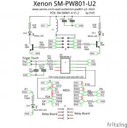
    I tried that, but as you can see in the schematic I drew, both CEN and EN are tied to VCC.
    Couldn't get the reader Program start/synch.

    And I cannot solder this small, can only flash OTA unfortunately.
    Thanks for your help with these, hope to get them going.
  • ADVERTISEMENT
  • #4 20819236
    p.kaczmarek2
    Moderator Smart Home
    You can do the reset without CEN.
    Just:
    1. connect common GND, RX and TX and 3.3V
    2. start flasher tool
    3. disconnect 3.3V (you can also connect 3.3V from the BK7231 side to GND for a second, just remember, the BK7231 side, not the power supply one! That would make a short circuit!)
    4. reconnec that 3.3V from BK7231 to 3.3V from power supply
    The flasher should "get bus" correctly. I've tested it many times.

    These days I do not even use CEN/EN for flashing.
    Helpful post? Buy me a coffee.
  • #5 20824742
    omniron
    Level 10  

    Ok, will try that, thanks!
    Should I use
    ltchiptool
    or
    bk_writer1.60 ??
  • #6 20824911
    p.kaczmarek2
    Moderator Smart Home
    Please only keep using tested tools, unproven tools can brick your device.
    Here are our tutorials:
    https://www.youtube.com/@elektrodacom
    Here is our newest flasher:
    https://github.com/openshwprojects/BK7231GUIFlashTool
    Here is a sample of WB3S flashing:


    Here is a sample of CB2S flashing:


    Helpful post? Buy me a coffee.
  • #7 20825505
    omniron
    Level 10  
    Watched videos etc, connected RX to TX and versa, used 3.3V USB serial.
    Can see serial data at 115200 Baud like

    V:BK7231S_1.0.5
    CPSR:000000D3
    R0:ADFDA1BB
    R1:637DADAF
    R2:CCDBD74E
    R3:62A7FA76
    R4:2ADF9C3F
    R13:C3FFDDC3
    R14(LR):FFDE5AD5
    ST:C1C54D64
    J 0x10000
    prvHeapInit-start addr:0x426670, size:104848
    [01-01 18:12:15 TUYA Debug][uni_thread.c:215] Thread:sys_timer Exec Start. Set to Running Status
    [01-01 18:12:15 TUYA Err][online_log_serv.c:280] log stats ufread fail.
    [01-01 18:12:15 TUYA Debug][online_log_serv.c:540] log serv init success
    [01-01 18:12:15 TUYA Debug][tuya_device.c:180] < TUYA IOT SDK V:2.0.0 BS:30.05_PT:2.2_LAN:3.3_CAD:1.0.2_CD:1.0.0 >
    < tuya_iot_lib BUILD AT:2018_12_05_17_03_30 BY tuya_iot_team AT 8710_2M >
    IOT DEFS < WIFI_GW:1 DEBUG:1 KV_FILE:0 SHUTDOWN_MODE:0 LITTLE_END:1 TLS_MODE:2 ENABLE_LOCAL_LINKAGE:0 ENABLE_CLOUD_OPERATION:0 ENABLE_SUBDEVICE:0 ENABLE_ENGINEER_TO_NORMAL:0 OPERATING_SYSTEM:2 ENABLE_SYS_RPC:0 TY_SECURITY_CHIP:0 RELIABLE_TRANSDAR:RELIABLE_TRANSDAR ENABLE_LAN_ENCRYPTION:1 ENABLE_SIGMESH:0 >

    [01-01 18:12:15 TUYA Debug][tuya_device.c:181] oem_bk7231s_rnd_switch:1.0.6
    [01-01 18:12:15 TUYA Notice][tuya_device.c:182] firmware compil2A at Apr 14 2020 14:27:29
    0xcb 0x9e 0x3d 0xa4 0x0 0x62 0x9d 0xa3 0x65 0xf2 0x8d 0xbf 0xe4 0xb9 0x3f 0x35
    10:23:11: [01-01 18:12:15 TUYA Notice][tuya_main.c:193] **********[oem_bk7231s_rnd_switch] [1.0.6] compil2A at Apr 14 2020 14:27:24**********
    [rx_iq]rx_amp_err_rd: 0x005
    [rx_iq]rx_phase_err_rd: 0xffffff26
    [rx_iq]rx_ty2_rd: 0x017
    *********** finally result **********

    tried the flasher but it would just loop for the "bus"
    checked with my scope to see how the signals look, all fine, both ways.
    rebooted with suggested methods, long and short, no change.
    Just to make sure, removed the 10K pullup at RXD2, no change, loop for the "bus".

    It's insane how much time and effort we both wasted on this.
    Sorry for our efforts, it just doesn't work.
    Is there a OTA way to get this flashed?
    Thanks
  • ADVERTISEMENT
  • #8 20825513
    p.kaczmarek2
    Moderator Smart Home
    We will flash it soon, we just need to work a bit more.

    I think you may be using wrong port.

    TXD2/RXD2 is debug log output, here you can read that log.

    TXD1/RXD1 is flashing port.

    Are you using TXD1/RXD1 for flashing?

    Can you make a photo of your circuit?
    Helpful post? Buy me a coffee.
  • ADVERTISEMENT
  • #9 20825801
    omniron
    Level 10  
    Yes, I was using the second serial port, bummer!
    So another soldering session and now this:

    Backup name is set to test14.
    Starting read!
    Now is: Monday, November 20, 2023 11:32:07 PM.
    Flasher mode: BK7231N
    Going to open port: COM11.
    Serial port open!
    Getting bus... (now, please do reboot by CEN or by power off/on)
    Getting bus success!
    Going to set baud rate setting (115200)!
    Will try to read device flash MID (for unprotect N):
    failed with serial.BytesToRead 0 (expected 15)
    The beginning of buffer in UART contains data.
    Failed to read device MID!
    Going to start reading at offset 0x00...
    Reading 0x00... Got exception: System.Threading.ThreadAbortException: Thread was being aborted.
    at Microsoft.Win32.UnsafeNativeMethods.ClearCommError(SafeFileHandle hFile, Int32& lpErrors, COMSTAT& lpStat)
    at System.IO.Ports.SerialStream.get_BytesToRead()
    at System.IO.Ports.SerialPort.get_BytesToRead()
    at BK7231Flasher.BK7231Flasher.Start_Cmd(Byte[] txbuf, Int32 rxLen, Single timeout) in W:\GIT\BK7231GUIFlashTool\BK7231Flasher\BK7231Flasher.cs:line 423!
    Exception caught: System.Threading.ThreadAbortException: Thread was being aborted.
    at BK7231Flasher.BK7231Flasher.Start_Cmd(Byte[] txbuf, Int32 rxLen, Single timeout) in W:\GIT\BK7231GUIFlashTool\BK7231Flasher\BK7231Flasher.cs:line 500
    at BK7231Flasher.BK7231Flasher.readSector(Int32 addr) in W:\GIT\BK7231GUIFlashTool\BK7231Flasher\BK7231Flasher.cs:line 1487
    at BK7231Flasher.BK7231Flasher.readSectorTo(Int32 addr, MemoryStream tg) in W:\GIT\BK7231GUIFlashTool\BK7231Flasher\BK7231Flasher.cs:line 1344
    at BK7231Flasher.BK7231Flasher.readChunk(Int32 startSector, Int32 sectors) in W:\GIT\BK7231GUIFlashTool\BK7231Flasher\BK7231Flasher.cs:line 1212
    at BK7231Flasher.BK7231Flasher.doReadInternal(Int32 startSector, Int32 sectors) in W:\GIT\BK7231GUIFlashTool\BK7231Flasher\BK7231Flasher.cs:line 1335
    at BK7231Flasher.BK7231Flasher.doRead(Int32 startSector, Int32 sectors) in W:\GIT\BK7231GUIFlashTool\BK7231Flasher\BK7231Flasher.cs:line 780
    Backup name is set to test15.
    Starting read!
    Now is: Monday, November 20, 2023 11:33:16 PM.
    Flasher mode: BK7231N
    Going to open port: COM11.
    Serial port open!
    Getting bus... (now, please do reboot by CEN or by power off/on)
    Getting bus success!
    Going to set baud rate setting (115200)!
    Will try to read device flash MID (for unprotect N):
    failed with serial.BytesToRead 0 (expected 15)
    The beginning of buffer in UART contains data.
    Failed to read device MID!
    Going to start reading at offset 0x00...
    Reading 0x00... failed with serial.BytesToRead 0 (expected 4111)
    The beginning of buffer in UART contains data.
    Failed! There was no result to save.
    Backup name is set to test16.
    Starting read!
    Now is: Tuesday, November 21, 2023 12:27:41 AM.
    Flasher mode: BK7231N
    Going to open port: COM11.
    Serial port open!
    Getting bus... (now, please do reboot by CEN or by power off/on)
    Getting bus failed, will try again - 0/100!
    Getting bus failed, will try again - 1/100!
    Getting bus failed, will try again - 2/100!
    Getting bus failed, will try again - 3/100!
    Getting bus success!
    Going to set baud rate setting (115200)!
    Will try to read device flash MID (for unprotect N):
    failed with serial.BytesToRead 0 (expected 15)
    The beginning of buffer in UART contains data.
    Failed to read device MID!
    Going to start reading at offset 0x00...
    Reading 0x00... failed with serial.BytesToRead 0 (expected 4111)
    The beginning of buffer in UART contains data.
    Failed! There was no result to save.

    I checked power, steady 3.25V, did many short/long resets, it always gets stuck at
    "Reading 0x00..."

    By now I probably could have made some silicon chips out of sand and heated some stones for the metals and played with some oil to get the plastics and be done with it all.

    Moderated By p.kaczmarek2:


    I can see now that you used BK7231N mode for BK7231T... no wonder that it failed! Next time, please make sure you are using BK7231N mode for BK7231N chips and BK7231T mode for BK7231T chips....
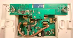
  • #10 20825871
    p.kaczmarek2
    Moderator Smart Home
    Can you try with bkWriter 1.60, just make sure to first read 2MB of device flash, to get a 2MB file that I can extract GPIO from?
    Helpful post? Buy me a coffee.
  • #12 20827028
    p.kaczmarek2
    Moderator Smart Home
    You need to enter 0x200000 in read lenght
    Helpful post? Buy me a coffee.
  • #13 20827057
    omniron
    Level 10  
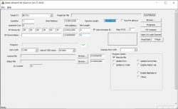
    User interface of Beken Writer V1.60 software used for programming microcontrollers.
    It was all default, I don't see read lenght, are you talking about "Operate Length"?
    What about "Start Address"?
    Screenshot of Beken Writer V1.60 software with various configuration settings for a device.
  • #14 20827066
    p.kaczmarek2
    Moderator Smart Home
    Do not change start address, it will wrap, but it will be okay. Just set operate length to 2 megabytes. Then if you provide flash 2MB dump here, I can try to decode GPIO config for that.

    You can also then flash OpenBeken.
    Helpful post? Buy me a coffee.
  • #16 20827147
    p.kaczmarek2
    Moderator Smart Home
    The following read is correct. Good job!
    Code: JSON
    Log in, to see the code

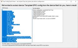
    Extracted GPIO (it seems NETLEd failed to extract):
    
    Device configuration, as extracted from Tuya: 
    - Button (channel 1) on P24
    - Relay (channel 2) on P9
    - Button (channel 2) on P10
    - Relay (channel 1) on P6
    Device seems to be using WB3S module, which is using BK7231T.
    And the Tuya section starts at UNCOMMON POSITION 1953792
    

    Now you can flash OBK...

    Added after 2 [minutes]:

    @omniron btw I also noticed now why previously flash read failed. You used BK7231N mode to read BK7231T... no wonder that it didnt work.
    Helpful post? Buy me a coffee.
  • #17 20827155
    omniron
    Level 10  

    Super!
    Finally.
    Thank you for your patience, I was going to drop that days ago.

    Sorry about BK7231N mode vs BK7231T, don't know where to set that??
    Should I make another read just to make sure?

    I have several of these and must program them OTA, can't open them one by one.
    Is that possible? If not, I have to return them.

    But since this is open and wired, how do I go ahead and flash this one with OBK?
    The videos were a bit generic.
    Thanks

    Added after 2 [minutes]:

    Yes, I noted WB3s in the schematic above
    https://www.elektroda.com/rtvforum/topic4015180.html#20818224
  • #18 20827359
    p.kaczmarek2
    Moderator Smart Home
    omniron wrote:

    Thank you for your patience, I was going to drop that days ago.

    We are here to help, don't give up, just ask on our forum


    omniron wrote:

    Sorry about BK7231N mode vs BK7231T, don't know where to set that??

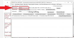
    Well:
    Screenshot of BK7231 Easy UART Flasher with the chip type selection option highlighted.

    omniron wrote:

    Should I make another read just to make sure?

    The created binary is 100% correct, there is no need for that.

    omniron wrote:

    I have several of these and must program them OTA, can't open them one by one.
    Is that possible? If not, I have to return them.

    It should be possible since we got 2MB flash dump of one device, I will try to do the preparations and ask the guys on Github for a profile, I will post futher instructions later.

    omniron wrote:

    But since this is open and wired, how do I go ahead and flash this one with OBK?

    Yes, please flash it, then we will configure it
    Helpful post? Buy me a coffee.
  • #19 20827866
    omniron
    Level 10  

    That would be great!
    If it was just about the template couldn't we just use the schematic I made?
    I hooked up the unit again and tested it with the other flash program and it worked as you said, mostly probably because of the swapped serial ports, right?
    Screenshot of Tuya Config Quick Viewer showing device configuration in JSON format and GPIO section description.


    I'm going to hook up the other units (with serial #1) especially this one:
    https://www.elektroda.com/rtvforum/topic3958242.html#20803474
    thanks
  • Helpful post
    #20 20828299
    p.kaczmarek2
    Moderator Smart Home
    It's not just about template, we need 2MB dump to flash next pieces by OTA.

    Here is a guide for flashing device via WiFi, without soldering wires:
    https://www.elektroda.com/rtvforum/topic4016459.html#20827829
    For your device, you need to use Xenon SM-PW801-US Wall Outlet profile.
    Helpful post? Buy me a coffee.
  • #22 20829348
    omniron
    Level 10  

    My unit was still connected by wires so I flashed it (after the backups), as mentioned above.
    Then I reinstated the template with the backup.
    Went to the unit's website, etc.
    Now all works fine, thanks again!
  • #23 20838803
    omniron
    Level 10  

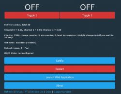
    I'm trying to rename the buttons of the freed Xenon SM-PW801-U2:

    User interface with two red buttons labeled Toggle 1 and Toggle 2 and technical information.

    In Tasmota it was a simple
    WebButton1 xyz (I tried that, thought commands are compatible)
    WebButton2 zyx

    So I researched
    https://github.com/openshwprojects/OpenBK7231T_App/blob/main/docs/commands-extended.md
    which talks about
    toggler_name0
    toggler_name1 etc.

    That command didn't work, so I tried
    https://www.elektroda.com/rtvforum/find.php?q=toggler_name

    None of those worked either.

    Question, how do I change the names of these buttons please???
  • Helpful post
    #24 20838808
    p.kaczmarek2
    Moderator Smart Home
    it's for toggler driver.
    You might rather use:
    
    setChannelLabel 1 Xyz
    
    Helpful post? Buy me a coffee.
  • #25 20838941
    omniron
    Level 10  
    Got it, now that this is not a toggle unit, how do I get rid of the "Toggle" text in the labels?
    Thanks! (for all)
  • Helpful post
    #26 20838965
    p.kaczmarek2
    Moderator Smart Home
    Helpful post? Buy me a coffee.
  • #27 20839170
    omniron
    Level 10  

    So cool!
    I really searched that page for "name" and "text" as mentioned, never thought of "label."
    Thanks
  • #29 20950173
    omniron
    Level 10  

    I found that the blue LED on the device (P1 please see schematic at the top) is not mentioned in the unit's template.
    Had it wrong in the schematic anyway (corrected).
    It was always on, tested it with WifiLED at P1 (RXD2) and it works/blinks!
    Could this please be added to its template?
  • #30 20950196
    p.kaczmarek2
    Moderator Smart Home
    omniron wrote:

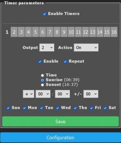
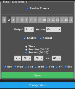
    Maybe I didn't search well the code on GitHub, does a sunset/rise feature exist for Tuya chips?

    It has been added recently, please see this topic:
    OpenBeken Scripting - Time and scheduling with NTP and addClockEvent


    omniron wrote:
    I found that the blue LED on the device (P1 please see schematic at the top) is not mentioned in the unit's template.
    Had it wrong in the schematic anyhow (corrected).
    It was always on, tested it with WifiLED at P1 (RXD2) and it works/blinks!
    Could this please be added this to it's template?

    Ok, so the final template is:
    Code: JSON
    Log in, to see the code


    I've added it to our devices list.
    Helpful post? Buy me a coffee.

Topic summary

The discussion revolves around flashing the OTA (Over-The-Air) firmware on the Xenon SM-PW801-U2 dual in-wall outlet, specifically addressing issues related to low range and quality concerns with the device. Users share methods for flashing, including UART connections and the necessity of obtaining a 2MB flash dump for successful OTA updates. Various tools such as bk_writer and ltchiptool are discussed, with emphasis on using reliable methods to avoid bricking the device. The conversation also touches on extracting GPIO configurations and modifying button labels in the firmware. Additionally, users express frustrations with the manufacturer's support and the device's performance, while seeking solutions for programming multiple units without physical access.
Summary generated by the language model.
ADVERTISEMENT