logo elektroda
logo elektroda
X
logo elektroda

[BK7231N/CBU] Tuya TH01? Generic Wi-Fi Temperature & Humidity Sensor [CHT8310]

divadiow 22368 128
ADVERTISEMENT
  • ADVERTISEMENT
  • ADVERTISEMENT
  • #94 21183776
    divadiow
    Level 34  
    >>21183750

    ahhh. there's me thinking it an edit and PR thing, OK. thanks
  • #95 21184836
    divadiow
    Level 34  
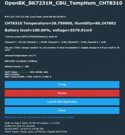
    I thought I'd dig out the TH01 with CHT8310 that was the subject of the first post. It's not been flashed for a while, way before the driver refactor. Thought I'd post before and after for no real reason other than to demonstrate the differences and any issues experienced in the process.

    No battery or CHT calibration config in autoexec, only backlog PowerSave 1; startDriver battery; startDriver NTP; startDriver CHT8305
    Before - 1.17.474
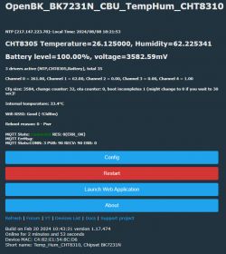
    OpenBK software interface for CHT8310 displaying temperature, humidity, and battery level data. Screenshot of module configuration settings showing P20, P21, and P22 connections.

    After - 1.17.652
    Screenshot of the OpenBK device configuration panel with CHT8310 sensor. Screenshot of pin configuration for CHT83XX sensor.

    and with no autoexec or startup commands
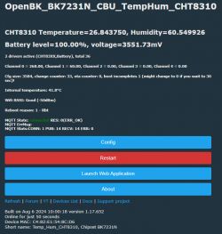
    OpenBK interface screen displaying CHT8310 data, including temperature, humidity, and battery level.

    so no issues.

    Added after 1 [hours] 39 [minutes]:

    @insmod I'm just testing CHT_Alert on this CHT8310 and I went with something quite high as a detected alert to wake on - +20 degrees. Is this an acceptable value as it doesn't seem to acknowledge the increase in temperature increases above +20 in testing with a heatshrink hot air gun.

    CHT_Alert 20 5 2 also tried with CHT_Alert 5 5 2 I note the example given is CHT_Alert 0.5 5 2

    My complete autoexec for testing

    Code: Text
    Log in, to see the code


    Added after 7 [minutes]:

    or even with CHT_Alert 0.9 5 2
  • #96 21184992
    insmod
    Level 22  
    >>21184836 Does it work with 0.1?
    Try dInput on P7
  • #97 21185005
    divadiow
    Level 34  
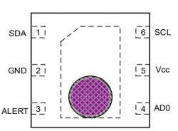
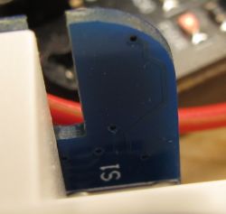
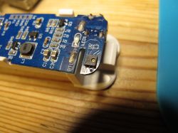
    I just thought of something obvious. I hadn't actually confirmed the alert pin goes anywhere on this device. The original fw does not have any pin info, so I can't confirm with alt_pin_pin presence in the extraction json. I'm not getting continuity from alert leg to any CBU contacts but it looks like it goes somewhere. I'll try to trace and try +0.1

    Close-up of a circuit board with visible electronic components.

    Diagram of integrated circuit pins labeled SDA, GND, ALERT, AD0, Vcc, SCL.

    Close-up of a section of a circuit board with the S1 marking and a red wire in the background.

    also, how does the driver know which GPIO the alert is on or is the alert over i2c?
    but if it's over i2c why's there an alert pin?

    Added after 9 [minutes]:

    no waking with dInput set on P7 with unused channel 9 (what is the significance of that?) - tested with CHT_Alert 10 5 2
  • ADVERTISEMENT
  • #99 21185014
    divadiow
    Level 34  
    insmod wrote:
    Pindeepsleep will wake from any pin, assuming it is connected to mcu

    ah OK. makes sense. I'll do more testing.

    Added after 18 [minutes]:

    so you have identical device? dInput or dInputNoPullUp? dsedge 0 or anything?
  • Helpful post
    #100 21185030
    insmod
    Level 22  
    >>21185014 Yes, it is identical. Just dinput, and nothing else.
  • #101 21185032
    divadiow
    Level 34  
    ok sure, thanks. and yes, continuity from alert leg to R7 then onwards to P7
  • #102 21185468
    p.kaczmarek2
    Moderator Smart Home
    insmod wrote:
    Pindeepsleep will wake from any pin, assuming it is connected to mcu. I traced the pin to P7. dInput is probably needed to set

    I think this is incorrect. Only certain input pins are waiting for wakeup signal. So, if you want the device to be woken up by given pin, you need to set pin role.
    Search for setGPIActive in:
    https://github.com/openshwprojects/OpenBK7231T_App/blob/main/src/new_pins.c
    Helpful post? Buy me a coffee.
  • #103 21185477
    divadiow
    Level 34  
    I have an update I haven't posted.

    I did an OBK tools device reset, cleario etc and configured everything again. Device has been asleep all morning until I blasted it with hot air and it woke just now. CHT_Alert is currently CHT_Alert 20 5 2.

    It's gone to sleep now and I'm blasting it with hot air and it's not waking. Maybe I'll reflash or try lower differences. It's a shame the reboot reason can't reflect it waking from alert pin specifically.

    Added after 11 [minutes]:

    Can also try new driver with this, the only other CHT8310 I have I think

    https://www.elektroda.com/rtvforum/topic3971252-30.html#20980349
  • #104 21185609
    insmod
    Level 22  
    >>21185468
    From TX2
    
    ---deep sleep test param : 0x4080 0x4080 0x40364C 0x403654 3600 3
    ---enter deep sleep :wake up with gpio 0~31 ps: 0x4080 0x4080 
    ---enter deep sleep :wake up with gpio32~39 ps: 0x40364c 0x403654 
    ---enter deep sleep :wake up with   rosc  ps :3600 s
    

    Wake enabled from all pins, and I can wake it with a button click. Button is P14, set to Btn, not dInput.

    Though looking at the source (https://github.com/openshwprojects/OpenBK7231N/blob/master/platforms/bk7231n/bk7231n_os/beken378/func/power_save/manual_ps.c#L278), 0x4080 etc. is pin index map, so maybe not from all pins.
  • #105 21185643
    vincenzoernst1
    Level 6  
    @insmod

    can you print a fully working config plz?
  • ADVERTISEMENT
  • #106 21185662
    insmod
    Level 22  
    >>21185643
    
    {
      "vendor": "Tuya",
      "bDetailed": "0",
      "name": "Full Device Name Here",
      "model": "enter short model name here",
      "chip": "BK7231N",
      "board": "TODO",
      "flags": "1024",
      "keywords": [
        "TODO",
        "TODO",
        "TODO"
      ],
      "pins": {
        "7": "dInput;5;0",
        "8": "BAT_Relay;3;0",
        "14": "Btn;4;0",
        "16": "WifiLED_n;0;0",
        "20": "CHT83XX_SCK;0;0",
        "22": "CHT83XX_SDA;0;1",
        "23": "BAT_ADC;2"
      },
      "command": "backlog PowerSave 1; Battery_cycle 2; addEventHandler OnHold 14 stopallscripts; Battery_Setup 2800 4200 1.95",
      "image": "https://obrazki.elektroda.pl/YOUR_IMAGE.jpg",
      "wiki": "https://www.elektroda.com/rtvforum/topic_YOUR_TOPIC.html"
    }
    

    autoexec.bat
    
    addRepeatingEventID 30 -1 1337 DeepSleep 10
    waitFor MQTTState 1
    cancelRepeatingEvent 1337
    delay_s 5
    cht_alert 0.2 0 60 2
    pindeepsleep 7200
    

    I use it in conjunction with https://github.com/openshwprojects/OpenBK7231T_App/pull/1297, but it may be unstable for you.
    Battery_setup is for 18650, modify voltages if using 2xAAA
    Also I have a bad ADC on my sample, so voltage divider may also be different.
  • #107 21207734
    akosschneemaier
    Level 6  
    Hello, I am trying to configure this module but I ran into problems. I am running it from an external power supply, so I am not adding any sleep or power save values.

    Here is my config:
    
    {
      "vendor": "Tuya",
      "bDetailed": "0",
      "name": "Full Device Name Here",
      "model": "enter short model name here",
      "chip": "BK7231N",
      "board": "TODO",
      "flags": "1024",
      "keywords": [
        "TODO",
        "TODO",
        "TODO"
      ],
      "pins": {
        "7": "dInput;5;0",
        "8": "BAT_Relay;3;0",
        "14": "Btn;4;0",
        "16": "WifiLED_n;0;0",
        "20": "CHT83XX_SCK;0;0",
        "22": "CHT83XX_SDA;0;1",
        "23": "BAT_ADC;2"
      },
      "command": "backlog startDriver battery; startDriver NTP; startDriver CHT8305",
      "image": "https://obrazki.elektroda.pl/YOUR_IMAGE.jpg",
      "wiki": "https://www.elektroda.com/rtvforum/topic_YOUR_TOPIC.html"
    }


    My problems are:
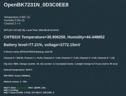
    1. On the main page the temperature values are not correct on the top section, but more or less correct in CHT8310 section:
    Screenshot of OpenBK7231N interface displaying various technical data.

    2. The board has a PW33 chip on it. I thought that it will stabilize the voltage, so if the input voltage from the battery is low, ex 2.5V it will convert it up to 3.3. However when the voltage is low I measure the same 2.5V on the battery poles and also on the CBU module (pin 14). Interestingly the module works with 2.5V. Is there some settings I have to configure to enable the voltage booster?

    Thanks
  • #108 21209151
    p.kaczmarek2
    Moderator Smart Home
    1. Change the channel types in the web app, because it seems like you're trying to, for example, map humidity to temperature channel. Changing channel types will also help with HASS discovery

    2. Is the PW33 chip an LDO regulator (that only works with higher voltages) or a step up converter (that can convert lower voltages to target voltage like 3.3V)? Do you measure 2.5V on the CBU VDD and GND pins? How PW33 looks like?
    Helpful post? Buy me a coffee.
  • #109 21210073
    akosschneemaier
    Level 6  
    >>21209151 Thank you! I adjusted the channels and temperature and humidity is fine now. Not sure what to select for the battery.

    I guessed that the PW33 is only an LDO :( Yes I did measure 2.5 on the CBU chip, but going to check again and I will also send a picture of the pw33
  • #110 21213059
    akosschneemaier
    Level 6  
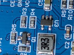
    >>21210073 Here is the picture of the PW33 Image of a circuit board with resistors and integrated circuits visible.

    It seems that running from external power source have a side effect: the BK temperature starts to influence the measurements. Example in a room where the temperature is ~26 C the device measures ~30C :(
  • #111 21213097
    vincenzoernst1
    Level 6  
    be sure, if the enclosure is closed, to place the box vertically (at best also when its open) and away from direct sunlight.
  • #112 21216618
    p.kaczmarek2
    Moderator Smart Home
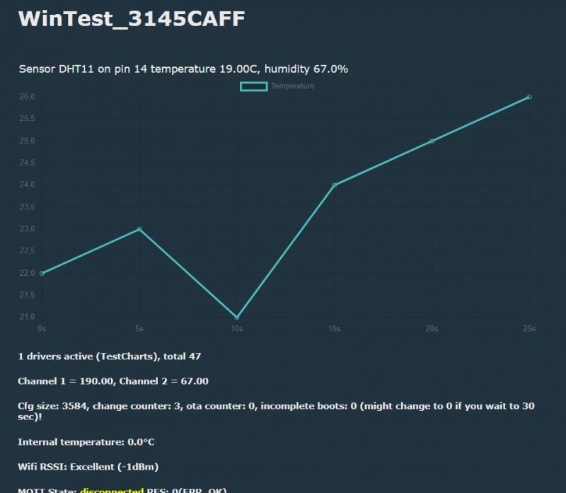
    I'm wondering how feasible would be drawing temperature/humidity charts on the device itself:
    Temperature graph showing data from DHT11 sensor on a dark background.
    The device for this use case would have to be powered from a power supply (obviously NOT batteries), but apart from that, the idea seems to make sense.
    Helpful post? Buy me a coffee.
  • #113 21330022
    GAAD
    Level 17  
    I reprogrammed one sensor today. Theoretically it works but it reported to HA once and no longer sends any more measurements. How do I configure the interval for sending measurements? Is it in the autoexec file? How do I send autoexec? Is there an option to configure temperature, humidity and battery alarms?

    Edit.
    My first sensor works. I adjusted autoexec and after the tests I am satisfied. It was time for the second one, the same. I uploaded OBK but a problem appeared while sending the configuration:

    
    {
      "vendor": "Tuya",
      "bDetailed": "0",
      "name": "Full Device Name Here",
      "model": "enter short model name here",
      "chip": "BK7231N",
      "board": "TODO",
      "flags": "1056",
      "keywords": [
        "TODO",
        "TODO",
        "TODO"
      ],
      "pins": {
        "8": "BAT_Relay;3",
        "14": "DoorSnsrWSleep;4",
        "16": "WifiLED_n;0",
        "20": "CHT8305_SCK;0",
        "22": "CHT8305_SDA;1",
        "23": "BAT_ADC;2"
      },
      "command": "backlog",
      "image": "https://obrazki.elektroda.pl/YOUR_IMAGE.jpg",
      "wiki": "https://www.elektroda.com/rtvforum/topic_YOUR_TOPIC.html"


    Script execution log:

    Send started... send 0/13... send 1/13... send 2/13... send 3/13... send 4/13... send 5/13... send 6/13... send 7/13...FAILED! Invalid command "backlog setPinRole 20 CHT8305_SCK; setPinChannel 20 0".

    The newer version of OBK requires a config change for CHT8305:
    
    {
      "vendor": "Tuya",
      "bDetailed": "0",
      "name": "Full Device Name Here",
      "model": "enter short model name here",
      "chip": "BK7231N",
      "board": "TODO",
      "flags": "1024",
      "keywords": [
        "TODO",
        "TODO",
        "TODO"
      ],
      "pins": {
        "8": "BAT_Relay;3;0",
        "14": "DoorSnsrWSleep;4;0",
        "16": "WifiLED_n;0;0",
        "20": "CHT83XX_SCK;0;0",
        "22": "CHT83XX_SDA;0;1",
        "23": "BAT_ADC;2"
      },
      "command": "",
      "image": "https://obrazki.elektroda.pl/YOUR_IMAGE.jpg",
      "wiki": "https://www.elektroda.com/rtvforum/topic_YOUR_TOPIC.html"
    }
  • #114 21385791
    andresterf
    Level 2  
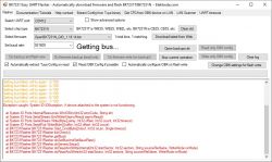
    Hi, I got one of these and after some trial flashed latest OBK without errors using the BK7231GUIFlashTool v5 and a CP2102 adaptor. But now it's bricked, won't boot (no led) and when I try to connect to serial it gets stuck in "Getting bus" cause power reboot don't work, and randomly gets the error below:

    Screenshot of BK7231 Easy UART Flasher application with communication errors.

    Any thoughts?

    Thanks in advance
  • #115 21385805
    GAAD
    Level 17  
    Simple question: do you have an external 3.3V voltage regulator?
  • #116 21385909
    p.kaczmarek2
    Moderator Smart Home
    I know this issue. Do you also hear USB unplug sound when you reset? This happens when you overload USB port. The inrush current when you connect power is too high and USB protection kicks in.

    @GAAD asked good question, but many things depend on your circuit and USB to UART converter. CP2102 doesn't look like something that can provide enough current at 3.3V for flashing.
    Helpful post? Buy me a coffee.
  • #117 21385957
    andresterf
    Level 2  
    >>21385805

    Negative, powering directly from CP2102 3.3V PIN, plugged to a USB 2.0 port. I don't have an external power supply at the moment, so I will try using a USB 3.0 port for the moment.

    Added after 6 [minutes]:

    >>21385909

    It flashed without errors, all green till the end, and I don't recall the adapter making any sound when it asked for the reboot, and powering off/on the device does nothing, but if any TX/RX jumper cable is touched the above error kicks in.

    For knowledge, when trying to flash the reboot step was a little trick, and whenever it failed I had to close BK Flasher and disconnect and reconnect the adapter from the PC, otherwise it would always fail to open the serial port.

    I will try the USB 3.0 port and also will look for an external power supply.

    Thanks!

    [UPDATE]
    Tried powering using 3.3V from and old Raspi but the device is dead, no led light or any kind of response!

    [UPDATE 2]
    Actually the device isn't dead, after tweaking around I figure out it is working but the led light is off, manage to configure web access and now I will mess around the configs.
  • #118 21395347
    lktrdng
    Level 4  
    >>21216618
    I think that you need it with a power supply or not depending on your resolution requirements. And because temperature is in general a "slow" variable, it might work with a lower sampling.
    I mean slow in a room, but in your drawing the temperature changed >2 degrees in 5 seconds!!! How was that possible?? Also your text says 19C and the drawing is on 26 :S. For sure I'm missing something :D
    You made me think in this possibility, I will explore this possibility (since my HA is not working :P) and report back my findings.
  • #119 21395390
    p.kaczmarek2
    Moderator Smart Home
    Remember that you can always check debug log output (TX2 pin) at 115200 baud if you are not sure if your device is working or not.
    Helpful post? Buy me a coffee.
  • #120 21402420
    rhizome
    Level 2  
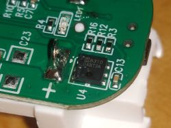
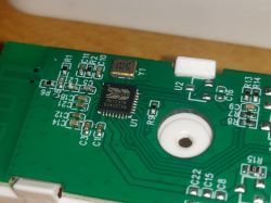
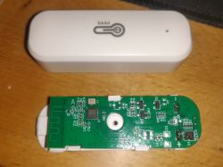
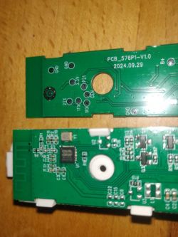
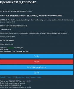
    Hi, I was wondering if I could get some help with my devices. They are certainly on BK7231N and the temperature chip seems to be a CHT8310. OpenBeken flash with the latest version with CloudCutter was without any problems. Whichever pin config I try I am getting 125°C Temperature and 100% humidity in sensor readings. How could I proceed with config?

    Close-up of a circuit board with a visible S8310 DABT3A integrated circuit.
    Close-up of a circuit board featuring a BK7231N chip and other components.
    Disassembled electronic device with a circuit board next to its casing.
    Two green circuit boards with various markings and components on a wooden surface.
    Screenshot of the OpenBK7231N software interface showing temperature and humidity reading issues.

Topic summary

The discussion revolves around the Tuya TH01 and its variations, particularly focusing on the CHT8310 temperature and humidity sensor. Users share experiences with flashing the device using OpenBK firmware, troubleshooting issues related to incorrect temperature and humidity readings, and configuring the device for optimal battery performance. Key topics include the use of the ALERT pin for power-saving features, calibration of sensor readings, and the integration of the device with Home Assistant via MQTT. Users also discuss the challenges of using the device with low battery levels and the need for proper pin configuration to avoid boot loops. The conversation highlights the importance of firmware updates and community support in enhancing device functionality.
Summary generated by the language model.
ADVERTISEMENT