logo elektroda
logo elektroda
X
logo elektroda
ADVERTISEMENT
Treść została przetłumaczona polish » english Zobacz oryginalną wersję tematu
  • #31 20856198
    efi222
    Level 19  
    The culprit is the oscilloscope.
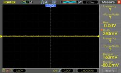
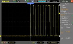
    It seems that the measurements are made from what he "sees" on the screen. And since the base is quite thick (noise?), it is included in the measurement. The peak value is different for different voltage ranges per division. This is what it looks like for the 5V and 2V range per plot. Best when measuring with a cursor. To sum up, it`s probably a problem with budget equipment (DSO5102BM)...
    It does not matter whether the probe is connected, shorted to ground or disconnected.
    5V range:
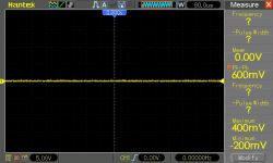
    Oscilloscope screen displaying signal waveform with annotated voltage values.
    2V range:
    Oscilloscope showing waveform with Pk-Pk value of 240 mV.
    cursor measurement. 500mV range:
    Oscilloscope screen showing voltage waveforms.
    Returning to the topic of WS2812B. The waveforms (amplitude) on the GPIO controlling the WS are identical with and without the tape connected. So nothing works retroactively with WS here. At least 5V. So ESP is safe in my opinion.

    And I must admit that the system I propose works at the border of the WS specification. With a 3.3 -> 5V driver, the system will certainly be reliable. I found an interesting patent on the Internet using a single WS2812. There is not always a driver at hand.
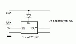
    Diagram showing the connection of a WS2812B LED with data and power.
    The only thing is that the WS +1 addresses need to be renumbered in the software
  • ADVERTISEMENT
  • #32 20856207
    krzbor
    Level 27  
    khoam wrote:
    Are you sure this information comes from the manufacturer`s documentation?

    All I know is that "All digital IO pins are protected from over-voltage". I assumed (maybe too optimistically) that it was done like in other UPs according to drawing. However, I may be wrong, as the documentation does not mention the method of security.

    Added after 1 [hour] 50 [minutes]:

    I found a very interesting website Link The author claims that the inputs can be easily connected to 5V. What`s even more interesting - the output can also work in 5V logic with an open drain configuration. I`m curious about your opinions on this matter. Anyway, I was wrong about the "Clamping diode" protection.
  • ADVERTISEMENT
  • #33 20856366
    efi222
    Level 19  
    I am familiar with the article. Actually, the manufacturer himself does not know or does not want to reveal the 5V resistance of the ESP inputs. It will be more convenient to maintain that it is not. Let me just say from my experience that it is quite a resistant MCU. I once powered it directly from a Li-ion battery (4.2V). It is true that the system was put to sleep and woken up every minute. He worked like this for several months. It was sending data via ESP-NOW. The disadvantage of this solution was the relatively high power consumption during Deep Sleep. About 1mA at 4.2V, which dropped with the battery discharge to the order of microamps.
  • #34 20856482
    khoam
    Level 42  
    Attached is the latest version of the document "ESP8266EX. Frequently Asked Questions" published by Espressif.
    On page 31 there is the following information:

    5/14. Are the GPIO pins 5V compatible?

    Well, they are not. While many applications may get away by using a resistor voltage divider or series resistor, we highly recommend using a proper logic level converter chip to interface with 5 V logic. Not doing so may lead to damage to the ESP8266 in the long run.
  • #35 20856494
    khoam
    Level 42  
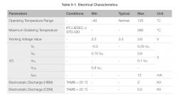
    From the document "ESP8266EX. Datasheet"

    Table displaying the electrical characteristics of ESP8266EX.

    Generally, I encourage you to read the manufacturer`s documentation instead of reading celebrity texts on the Internet :)

    Added after 20 [minutes]:

    krzbor wrote:
    Anyway, I was wrong about the "Clamping diode" protection.

    A little:

    " All digital IO pins are protected from over-voltage with a snap-back circuit connected between the pad and ground. The snap back voltage is typically about 6V, and the holding voltage is 5.8V. This provides protection from over-voltages and ESD. The output devices are also protected from reversed voltages with diodes. "
  • #36 20856835
    Jawi_P
    Level 36  
    These WS2812 diodes are a brilliant invention. A clock made of a chip and a strip of diodes. Apart from that, it`s nicely made, I didn`t think I would admire another watch :)
  • ADVERTISEMENT
  • #37 20856921
    efi222
    Level 19  
    Clock - You could say that it is one of the few measuring devices present in every home...
    Friend @Jawi_P, there is no point in admiring, just get to work :D . Eyesight weakens with age, and here are the big numbers...
    This is obviously a joke. There are plenty of watches on the market now. Here there is only satisfaction from building such a device. Although there are not many watches with NTP synchronization (including automatic summer-winter time).
  • #38 20857256
    tmf
    VIP Meritorious for electroda.pl
    Speaking of WS control... a few years ago I made Christmas lights on them, they are controlled from a 3.3V XMEGi and there is no problem at all - it works like a dream, even at -20 degrees :) Of course, I do not encourage anyone to go beyond the scope declared by the manufacturer. Here I simply made a mistake and forgot about the level translation, and since it worked, I discovered this error a few years later when I read the note for this diode more carefully. :)
  • ADVERTISEMENT
  • #39 20863804
    bumble
    Level 40  
    >>20853923
    The clock may be OK, but what are these lines under the numbers, where one is highlighted in red? I guess days of the week. But not described. For some people the first day of the week is Monday, for others it`s Sunday and that`s where everything gets mixed up. The lack of a date is also a disadvantage. It`s like a bedside lamp without a lampshade. That`s how I see it.
  • #40 20863874
    efi222
    Level 19  
    urkotrebor wrote:
    If I remember correctly, the library I used made it possible to read the values on individual diodes, so a feedback signal of 5V is tolerated by the ESP?

    I delved deeper into the topic of WS2812B. How are the settings of individual LEDs on the strip read? There is no physical feedback from WS to the MCU here.
    After assigning RGB or HSV values to the selected LED, they are written to and read from the CRGB table.
    Moreover, proof that physical reverse information does not exist is the use of a 3.3 -> 5V converter.
    Such a converter is unidirectional. Personally, I have not encountered a bidirectional converter for WS control.

    Added after 14 [minutes]:

    bumble wrote:
    I guess days of the week.

    There`s no need to guess. This is described in the article.
    bumble wrote:
    But not described

    It`s only seven lines. Easy to remember visually.
    bumble wrote:
    For some people the first day of the week is Monday, for others it is Sunday

    In the program code, the order of the days of the week can be set to your liking.
    bumble wrote:
    It`s like a bedside lamp without a lampshade.

    With the appropriate brightness setting, this watch can be successfully used for this purpose (additionally) :)

    Added after 4 [minutes]:

    bumble wrote:
    The lack of a date is also a disadvantage.

    The project did not include a calendar.
  • #41 20864063
    urkotrebor
    Level 21  
    I used this library https://github.com/adafruit/Adafruit_NeoPixel, there are two instructions whose names would indicate that they give feedback "getPixelColor()" and "getBrightness()".
    I admit, I haven`t tested them and I don`t know how they work.
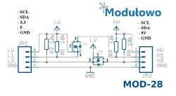
    As for the converter, I don`t know which one you use, I use this one https://abc-rc.pl/pl/products/konwerter-level...-4-kanaly-stanow-logicznych-spi-uart-arduino- 6191.html?query_id=1 and I assure you that it is bidirectional.
    I quickly found this diagram:
    Circuit diagram of a logic level converter with connection labels.
  • #42 20864072
    khoam
    Level 42  
    urkotrebor wrote:
    there are two instructions whose names would indicate that they provide feedback: "getPixelColor()" and "getBrightness()".

    This is "feedback" information from the buffer in RAM, where data about the current state of "pixels" is stored. Via this buffer you can send information to the LED strip "once". There is no communication the other way around.
  • #43 20866835
    Andrzej42
    Level 31  
    https://d2j2m4p6r3pg95.cloudfront.net/module_files/led-cube/assets/datasheets/WS2812B.pdf
    Is it so difficult to read? : WS2812 work in series with a maximum of 1024 pieces, you send packets of 24 bits to the input of the first one, where the first packet programs the last one and the last packet programs the first LED. So, when you arrange a shape, you have to remember which led is where.
  • #44 20866962
    efi222
    Level 19  
    It`s exactly as my friend writes. And here you can wonder why the "getBrightness()" instructions etc. were created.
    If the MCU sends data to the LED address, it stays there until the next instruction or until the power is turned off.
    Anyone have an idea?

    Another logical example:
    - turn on the switch to turn on the bulb.
    - check the condition of the switch.
    - if it is on, the bulb is on...
  • #45 20866986
    khoam
    Level 42  
    efi222 wrote:
    And here you can wonder why the "getBrightness()" instructions etc. were created.

    The explanation is in the Adafruit NeoPixel source code:

    " This is for high-performance applications where calling setPixelColor() on every single pixel would be too slow (eg POV or light-painting projects). There is no bounds checking on the array, creating tremendous potential for mayhem if one writes past the ends of the buffer. Great power, great responsibility and all that. "

    That is, for advanced users ;)
  • #46 20885923
    davidcpurdy
    Level 7  
    Thank you for sharing your project and explaining the details.

    I had been thinking about a clock project - analog 12- hour - and had considered just lots and lots of LEDs... but I think your use of the "mask" idea makes it more readable and better define (less "fuzzy"). The "segments" are super easy to read and interpret...

    Now I just have to buy the LED tape and do some planning + programming.
  • #47 20890680
    sq3evp
    Level 37  
    An interesting design, simple and effective.
    A cool idea to make a display with LEDs.

Topic summary

The discussion revolves around a user-created LED clock utilizing WS2812B LED strips, which synchronizes time via NTP servers. The clock features large digits (79 mm) and displays the days of the week. Participants commend the design and inquire about the availability of STL files for 3D printing. Technical aspects include the use of an ADC circuit for brightness adjustment and the challenges of controlling WS2812B LEDs with ESP8266, particularly regarding voltage levels and feedback mechanisms. Various suggestions for materials and methods to improve the display quality are shared, alongside discussions on the limitations of the ESP8266's ADC and the importance of using proper logic level converters for 5V compatibility.
Summary generated by the language model.
ADVERTISEMENT