logo elektroda
logo elektroda
X
logo elektroda

Another ELIVCO LSPA9: BSD342-2110 PCB with [LN882H] and [BL0937]

max4elektroda 3246 27
ADVERTISEMENT
  • This plug was already mentioned here
    and here is the very useful page about the LN882H.

    The inside is exactly the same PCB as mentioned here with another socket case and a different relay.
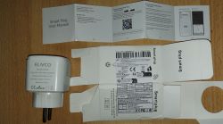
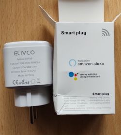
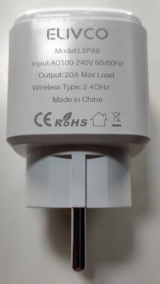
    ELIVCO LSPA9 smart plug with user manual and packaging ELIVCO smart plug with packaging.

    So, why another post? I think I might give some useful information here, so I hope it's o.k.
    (If there should not be a new post, for the same device, please move it into one of the other posts)

    First about opening the device:

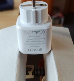
    The upper and lower part are lightly glued together and the pressure on the sides should break it open.
    I opened the case with help of a vice, so you can apply pressure on the whole sides.
    Just use some thick paper or cardboard to avoid marks on the case.
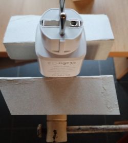
    Electric plug placed between two wooden boards. ELIVCO plug held in a vise, viewed from the socket side.
    Turn the plug to put pressure on both sides. You will hear a light crack when glue is broken; you might also support the pressure by some light bending of the socket.
    (If you hear a loud crack, you probably applied to much pressure ;-) but I already opened five devices and never broke one...)
    Just keep pressing and turning the sides until the device pops open.

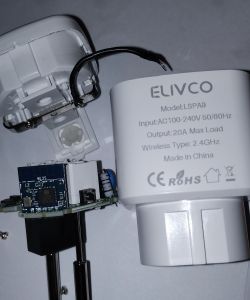
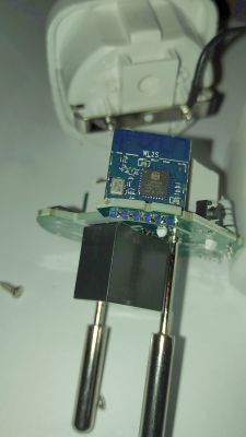
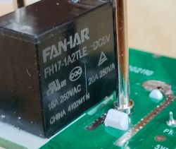
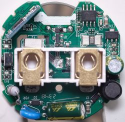
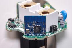
    The inside is a BSD342-2110 PCB with "WL2S" labeled LN882H module and BL0937 energy metering chip. The relay shows 16A and 20A, so it's your choice, what to believe ;-):
    ELIVCO model LSPA9 plug with removed casing, showing internal PCB with WL2S module.

    Close-up of PCB with LN882H module and markings. Image showing the inside of a device with a WL2S PCB. Image of a FANHAR FH17-1A2TLE-DC5V relay on a PCB.

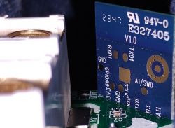
    The bootlog for the shipped firmware is visible on Tx1 (UART1 is on the back side of the WL2S module), but flashing is done via Rx0/Tx0 (soldered to main PCB).


    Now to some new findings (I hope): As I am a lazy guy, let me tell you, that in fact you only need to solder three wires :-)

    VCC (3.3 V)
    RX
    TX

    You can use the plugs power pin opposite to the LN882H module as GND - no need to solder here!
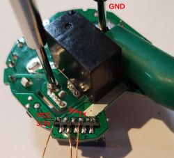
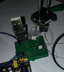
    Close-up of a PCB with labels VCC, RX, TX, and GND Breadboard with connected wires and USB module..
    If there was any doubt, now you know for sure that you should never try to use the free GPIOs outside the plugs case: For at least GND will be connected to the high voltage live wires!

    Regarding flashing you need to short pin A9 to GND - but this was not necessary for the whole flashing process:
    I shortened A9 for some seconds after powering the device up - you will see if you missed the point, if the device starts flashing its LED.
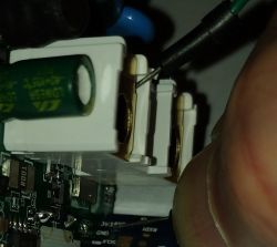
    Close-up of electronic components on a PCB with wires soldered to them.
    It works o.k. with the shown wires from a breadboard, for other plugs I used a testing pin from a multi-meter, this won't bend so easy.
    It didn't work every time, I had to give it some tries, but was successful with all plugs in the end.
    Remember, since we used the power pin for GND, we have it present on the upper outlet socket, as you can see on the picture.

    For you might need to retry several times: If your PCs keyboard is not reachable from the plug while shortening the pin, I had a small batch file running to retry every five seconds.

    Just to show off, I pimped my simple batch a bit ;-)

    @echo off
    echo List of serial ports (with some text about status):
    echo.
    echo and all .bin files
    dir *.bin  | findstr .bin
    echo.
    echo.
    mode | findstr COM
    echo.
    echo.
    
    :pset
    set p=-10
    set /p p="Enter COM-Port number: "
    if +%p% NEQ %p%   (
    	@echo please only provide numbers
    	goto pset
    )
    (mode | findstr COM%p%: >Nul || (
    	@echo COM%p% not found
    	goto pset
    ))
    
    :fset
    set /p f="Enter filename: "
    if NOT exist %f% (
    	@echo Can't find file %f%. Please chek and try again.
    	goto fset
    )
    
    :loop
     LN882H_CMD_Tool.exe COM%p% download flash 115200 0x0 %f%
     timeout /t 5
    goto loop


    Then flashing with the speed of 115200 (I didn't manage to use 200000, that might be, because of too long wires, the PCB not desoldered but still in the plugs PCB, or some other reason).


    Thanks again to all the brave people working on the Openbeken port for this chip!

    Here is my template for the device:
    Quote:
    {
    "vendor": "Elvico",
    "bDetailed": "0",
    "name": "Elvico LSPA9",
    "model": "LSPA9",
    "chip": "LN882H",
    "board": "BSD342-2110",
    "flags": "1024",
    "keywords": [
    "BSD342-2110",
    "LN882H",
    "BL0937"
    ],
    "pins": {
    "0": "LED_n;0",
    "3": "Btn;0",
    "7": "BL0937CF1;0",
    "10": "WifiLED_n;1",
    "11": "Rel;0",
    "12": "BL0937CF;0",
    "19": "BL0937SEL;0"
    },
    "command": "",
    "image": "https://obrazki.elektroda.pl/5522980200_1708165078.jpg",
    "wiki": "https://www.elektroda.com/rtvforum/topic4036567.html"
    }


    Please also see the posts by @divadiow Link and by @sithyoda Link.

    The flashing tool is present e.g. in the LN882H flashing guide by @p.kaczmarek2
    or can be downloaded here:
    https://gitee.com/lightningsemi/ln882h-docume...%BB%A4%E8%A1%8C%E5%B7%A5%E5%85%B7_V1.0.16.zip (use "save as" on the shown download link, for at least for me it would otherwise only show the raw binary - missing mime type I suspect)

    Have fun!

    Cool? Ranking DIY
    About Author
    max4elektroda
    Level 20  
    Offline 
    max4elektroda wrote 458 posts with rating 108, helped 21 times. Been with us since 2024 year.
  • ADVERTISEMENT
  • #2 20965704
    miegapele
    Level 15  

    Which AliExpress shop this was bought? I would like ln882h lspa9 form socket for my collection 😂
  • #3 20965724
    max4elektroda
    Level 20  

    It was bought at Digitaling Store, and this is the Link to the plug.

    But, since this was some weeks ago, you can never be sure, you will get the same device, if you order it now ;-)
  • #4 21004486
    Raufaser
    Level 10  
    I bought the same plug as OP. I can see on the order details that it is even the same item number on AliExpress.

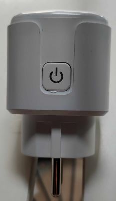
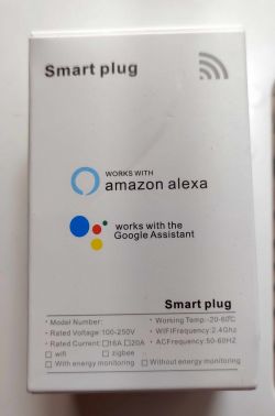
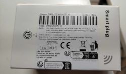
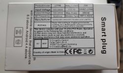
    Here is my plug and package:
    Close-up of an ELIVCO smart plug with technical specifications. White plug with a power button on the front. Smart plug packaging with Amazon Alexa and Google Assistant information. Label of Tuya smart plug packaging with SKU, barcode, and manufacturer information. Smart plug packaging with technical specifications and manufacturer information.

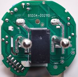
    And some high res pics of the internals. Maybe useful for someone:
    Close-up of the interior of an electronic USB plug showing components. Close-up of an electronic module WL2S mounted on a printed circuit board. Image of the interior of an electronic plug with visible circuit components and marking BSD34-202110.

    Before flashing the Open Firmware i dumped the original one:
    LSPA9_o...bin Download (1 kB) LSPA9_fl..h.bin Download (2 MB)

    Until now, everything works well :)
  • #5 21015608
    Raufaser
    Level 10  
    The device seems to be very unstable. Longest uptime was around 48h. It just disappears from the network after a certain amount of time.
    Also all firmwares from 1.17.513 and later are not really booting up. The instantly restart. Sometimes they run for the amount of time needed to reflash a different version via Webapp.

    Added after 9 [minutes]:

    I noticed that the firmwares >512 running OK when i only access the plug via Webapp. As soon as I try to access it via the normal Web-GUI it hangs for about 20 - 30 seconds.
  • ADVERTISEMENT
  • #6 21022643
    rufus4
    Level 10  
    Hi @ all,
    for me its working fine with latest version (OpenLN882H_1.17.521.bin) Web GUI and Web App are working smooth.
    Once I got kicked out of networkaccess after doing some settings with reboot. Only reflash to vendors FW did solve it. Dont know what the problem was.
    Stability I do have to test still. Playing arround since yesterday only.

    A other thing I want to ask.
    How do I need to set the button to control the relais manualy and what action does the button with the setting "3": "Btn;0" ?
  • #7 21022708
    max4elektroda
    Level 20  
    rufus4 wrote:

    A other thing I want to ask.
    How do I need to set the button to control the relais manualy and what action does the button with the setting "3": "Btn;0" ?

    This setting should control the button 😀!
    It defines pin 3 (A3) as control input for channel 0.

    If it doesn't work as expected, maybe you defined your relay to another channel (see the number after the relay, in this case pin 11 with channel 0: "11": "Rel;0", )?
    Or your layout is different, and you need to set another pin for it.
    Then you might want to use the pin doctor from web application to search the correct pin.
  • #8 21022878
    rufus4
    Level 10  
    thanks!

    I have the BSD34-202110 bord like @Raufaser . Yours is BSD342-2110 if this is correct?
    Channel is the same. Seems like button needs another pin setting then.
    ----------
    solved!
    The push-button on my device is crap. I had to press it with some more power to make contact.
    Well these thingies take a lot of attention. :)
    ----------

    Does start value for channel 0 with "-1" work for you?
    (I`m scared to try because last time messed up device with this setting.)

    --update--
    Kept my fingers crossed and did set channel 0 to "-1" for startup... and it works without any problems. :)
  • ADVERTISEMENT
  • #9 21023427
    max4elektroda
    Level 20  
    Just when I made it to try - yes it works, regardless if there is power loss or it's restarted via GUI ;-)
  • ADVERTISEMENT
  • #10 21023618
    rufus4
    Level 10  
    max4elektroda wrote:
    Just when I made it to try

    kkk... thanks anyway

    Next will hopefully be a working "powersave" on the LN882.
    Tomorrow I try to find some time to mesure power consumption of the hole unit from the AC side. I think it is too much at the moment. Device gets quiet hot.
    Microprocessor temperature is about 60°C with "powersave 0" inside LSPA9 enclosure. And around 40°C with "powersave 1".
    But after some time the device seems to fall a sleep with non responsing GUI. So it`s not working yet.
  • #11 21024659
    rufus4
    Level 10  
    Today I was playing arround with my multimeter to mesure the powerconsumption of the LSPA9.
    First I had to realise that powermesuring needs to be done with a osciloscope to get reliable results, because the consumption is not contant and has got fast changing low and hight peaks.

    But mesuring even with the multimeter high powerconsumption can be noticed on this device with the beta OpenFW without any working powersave mode.
    So its not recommended to use the device yet in a daily usecase. It`s getting just to hot.

    Mesured with a ammeter: LSPA9 without powersave, relais off 8,5mA and 12,5mA with relais on. That`s inbetween 2 and 3Watts!
    This is about the double of what I mesured of a Shelly Plug (16A)
  • #12 21024677
    Raufaser
    Level 10  
    Yo dawg, I heard you like power measurements. So i put a Beken in line with your Beken, so you can measure the power consumption of measuring the power consumption.

    🤣

    But seriously, how did you measure with your multimeter? And how would you do with a scope? I am interested in this too.
  • #13 21024780
    rufus4
    Level 10  
    I do have a good quality DMM from Brymen to measure inline and a good and payable clamp meter (UNI-T UT211B). They show +/- the same.
    With an oscilloscope I think you do it with a shunt resistance and measure before and after that. Then you get the voltage difference to calculate the amps. There you can measure and record all the spikes and as well average. I do have a beginners osci, but didn't find the time to play with it and learn how to measure this.

    Back to the LSPA9.
    I did flash original fw and this unwanted tuya app to see its consumption and it looks like not even them have got a powersave running. It's taking 8 and 12.5mA what is the same like with the OpenBekenFW.
    That's very interesting!
  • #14 21034099
    rufus4
    Level 10  
    --update and observations--
    PowerSave 1 still needs to be set manually after the device has booted. But my LSPA9 is stable since more than three days without any interrupts or hanging in the GUI. (OpenLN882H_1.17.530_OTA.bin)
    DHT still doesn`t work yet.
    All in all its not far away from good stability for daily use.
  • #15 21034356
    Raufaser
    Level 10  
    Good to hear that yours is running stable. I can report mine is running stable too. For almost a week now. It is in use 24/7 measuring the consumption of my "always on" Tiny-PCs 👍

    Software version and uptime information.
  • #16 21059991
    Raufaser
    Level 10  
    Is it possible to add the device to the device list? The Elvico LSPA9, that are in the list have different pin settings.
  • #17 21060004
    io2345
    Level 8  
    Has probably nothing to do with Hardware or Flashing, but might depend on the used Tasmota Firmware: How to switch this device from IObroker? I can read the device via MQTT and also can see a state "mqtt.0.<MQTT_Client_Topic>.0.get" alternating from 0 to 1 when switching the plug with button or from the Tasmota-Webpage. But changing this value in ioBroker doesn't change the state of the plug. Anyone with a solution?
  • #18 21063201
    io2345
    Level 8  
    With the help from some guys on ioBroker-Forum, I managed to get basic switching functionality in ioBroker: You have to create a manual entry in the mqtt.0 device-tree (using Expert Mode): mqtt.0.cmnd.<Client Topic name of the Device>.POWER
    After some time you will also get an additional entry mqtt.0.stat.<Client Topic name of the Device>.RESULT, which shows the state of the device in JSON type like "{"POWER": "OFF"}". This entry is automatically created.
    They said, that in Tasmota there should also an entry be automatically created
    mqtt.0.stat.<Client Topic name of the Device>.POWER
    but this is not the fact. I only get ...RESULT there.

    After adding the value POWER manually in the device-tree, you have to be patient. The device will switch occasionally for some minutes, while MQTT "balancing" takes place (I guess). Once the main page of the device shows in green "MQTT state: connected" and stays that way, things will be ok.

    Some issues: You can switch the device from within the field mqtt.0.cmnd.<Client Topic name of the Device>.POWER by sending payload "0" or "1" as number. Sending as logical value (boolean) does only work for "false" but not for "true". Same (but opposite way) applys to sending the string TOGGLE - it only works, if the device is currently in "off"-state.

    Next downside: If you switch the plug manually (using the hardware switch on the plug), the state of the plug does not change in ioBroker. You can't even change it by overwriting the POWER value with the desired number, so you have to use the opposite value first and then the desired value to change state.

    Any idea how to fix that?
  • #19 21063422
    max4elektroda
    Level 20  
    Sorry, I never used the plug like that, so I can't help here
  • #20 21064195
    io2345
    Level 8  
    Alright. Do you mean, you never switch the plug using the hardware button on the plug?
    Btw: Is there a data point for your plug that reflects the state of this button, meaning: indicating, if it is pushed? Can it be, that this input (information that button is pushed) isn't implemented yet? Maybe I have to ask @p.kaczmarek2 about that, right?
  • #21 21064249
    max4elektroda
    Level 20  
    io2345 wrote:
    Alright. Do you mean, you never switch the plug using the hardware button on the plug?

    No, I do use the button, too, but not mqqt...
    If I press the button, the relais switches and this is reflected in the GUI after the next update (every 3 seconds or so, when power metering values are updated)
  • #22 21064281
    io2345
    Level 8  
    I see - you're only using the device's webpage to switch.

    All the others, who do use MQTT: Does your device tree change the values in
    mqtt.0.cmnd.<topic>.POWER
    and
    mqtt.0.stat.<topic>.RESULT
    when switching the plug with the hardware button?
  • #23 21064315
    Raufaser
    Level 10  
    I am using all my sockets with MQTT and Homeassistant. It works out of the box. When switching on or off using the hardware button, the view in homeassistant is updated accordingly.

    Here is what happens on MQTT when switching the socket on and off using the hardware button:

    Message 8 received on smartsocket003/0/get at 12:38 PM:
    0
    QoS: 1 - Retain: false
    
    Message 7 received on smartsocket003/0/get at 12:38 PM:
    1
    QoS: 1 - Retain: false


    smartsocket003 is the client topic set in the socket's MQTT config form.
  • #24 21064461
    io2345
    Level 8  
    You're right, it does send MQTT message on button press, according to the Device's webpage log.

    The solution for ioBroker is much easier than expected: There is no need to have cmnd- and stat-tree in mqtt-adpater-tree at all.
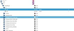
    Instead, create a new entry in the same folder, where the "get" value is displayed, with the only difference that it says "set".
    So, all you do is create a new state with name "set" as type "number" and role "variable" (readable and writeable) under the objects-tree

    mqtt.0.<your_client_topic_name>.0.

    Screenshot of ioBroker folder tree highlighting the get and set states.

    The "set" value is used to actually switch the device remotely, whereas the get value reflects the current state of the plug, which can also be changed by pressing the hardware button on the plug.
  • #25 21067066
    io2345
    Level 8  
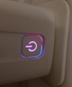
    Last (?) question: The LED on the plug is in Tuya-Version blue when plug is switched off and red when plug is on.
    In OpenBK version the LED is blue when off, but purple when on, because both blue and red LED inside are lit. Can this be changed to red?

    Power button icon on a plug with purple backlight.
  • #26 21067095
    rufus4
    Level 10  
    You can set "WifiLED_n" to "WifiLED". Then WifiLED is only lit while connection process.
  • #27 21067125
    io2345
    Level 8  
    Thank you, much better: LED off when Power off, LED red when Plug has Power. Perfect.
  • #28 21067385
    max4elektroda
    Level 20  
    ... or, if you like the Tuya style, you can set A10 to "LED" and it will be blue if power is off.
    (If you use the plug in place with low light, I like to find the button without turning on the light ...)
    That's the good point in using OpenBeken: Just configure it to fit yor needs ;-)

Topic summary

The discussion revolves around the ELIVCO LSPA9 device, specifically the BSD342-2110 PCB variant equipped with LN882H and BL0937 components. Users share insights on opening the device, stability issues, and firmware performance. Some report successful operation with the latest OpenLN882H firmware, while others experience instability and high power consumption. Users discuss power measurement techniques, MQTT integration with ioBroker, and LED behavior customization. The conversation highlights the importance of firmware versions and settings for optimal device performance.
Summary generated by the language model.
ADVERTISEMENT