 .
.
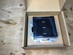
Today I am presenting a firmware change and connection to Home Assistant for another product in the Avatto series. This time it will be a triple light switch based on CB3S. The situation here will be similar to the white single model - I will need to detect the GPIO configuration using the tool GPIODoctor .
Purchase N-TS10-EU-B3 .
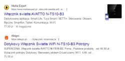
This triple switch is available to buy for around £75:
 .
.
This is a relatively good price, especially as this is the triple version, i.e. with three touch buttons and three relays inside. In addition, all the time there is talk of buying from a distributor in our country.
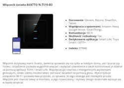
Dimensions:
 .
.
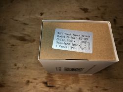
Packaging, markings:

 .
.
Instructions:
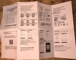
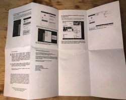
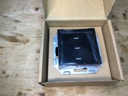
Kit contents:
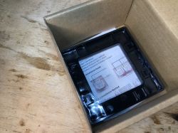
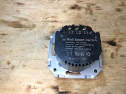
 .
.
ADVERTISEMENT
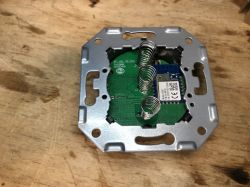
Interior N-TS10-EU-B3 .
The product is worth comparing with its brother version, the single, white, Avatto N-TS10-W1 which I have already described.
 .
.
PCB designation:
EU_CBL_CB_SV2
T=1.6MM
20220409
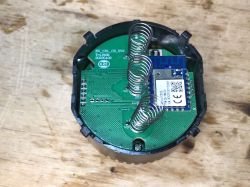
There are some pads visible - maybe for programming?
 .
.
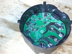
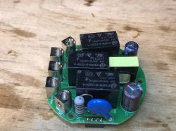
Relay and power supply board - the power supply is based on a DP2525, as in similar products in this series. You can also see a 3.3V LDO regulator and three transistors (designation J3Y, a classic).
 .
.
The relays are three pieces of JY32FN-S-DC5V-A:
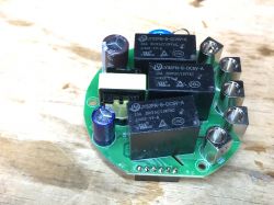 .
.
Yes, here is already a small flyback power supply. There is no non-isolated step-down converter here as in other products of this type. Overview diagram of the power supply:
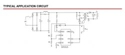 .
.
 .
.
PCB designation of the power supply/relays: YD3L_WF_DV5 20220412.
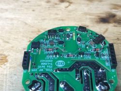 .
.
There are four LEDs inside - one per relay and an additional LED from WiFi/steaming status:
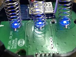
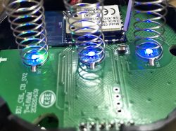
Change firmware N-TS10-EU-B3 .
OpenBeken upload:
https://github.com/openshwprojects/OpenBK7231T_App
According to the flasher instructions:
https://github.com/openshwprojects/BK7231GUIFlashTool
You can also watch videos on the Elektroda com channel:
https://www.youtube.com/@elektrodacom
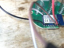
The CB3S/WB3S leads are online, I soldered the leads to GND, 3.3V, RX1 and TX1:
 .
.
This time my Flasher did not import the Tuya JSON configuration correctly.
Here are the manually specified GPIO roles:
P6 - Rel 1
P8 - Rel 2
P9 - Rel 3
P26 - Green LED
P7 - Btn 1
P10 - Btn 2
P24 - Btn 3
The LEDs are together with the relays on the same pins.
Code: JSON
Summary
The firmware change went without any problems. Slightly worse was the configuration. This time it failed to extract the JSON Tuya configuration batch from the 2MB copy so I had to guess it manually using the GPIODoctor tool. Fortunately, this only needs to be done once, and I've already done it for you, so if you want to flash such a product, you can copy the template from me.
On the other hand, what to do next after flashing is already shown to you by, among others, our Youtube channel Elektroda com:
https://www.youtube.com/playlist?list=PLzbXEc2ebpH0I8m_Cfbqv1MTlQuBKYvlx
If you have any problems or questions, please write, I will try to help you.
Cool? Ranking DIY Helpful post? Buy me a coffee.


