In this topic, I will modify the N-TS10-W1 light switch based on the CB3S module. In contrast to previous switches In this series, however, it will not be possible to automatically configure GPIO based on the Tuya partition, so I will have to discover it myself using the GPIODoctor tool, which I will also present here.
Purchase Avatto N-TS10-W1
This switch probably only distinguishes the unusual style of the front. At least it is not disfigured with the manufacturer`s logo, as is the case with, for example, the QTouch brand. The switch itself belongs to the N-TS10 series and costs PLN 70 in our country:
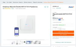
Product description - as usual - but we will change the firmware anyway, because I tested the Tuya application a long time ago:
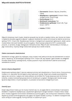
Specifications, dimensions, etc.:
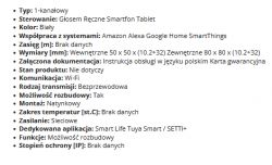
Here, I have a plus for the seller for writing "no data available" within WiFi range, it`s probably better than declaring values that are then not reflected in practice. WiFi is quite capricious and its reliability does not come close to that of a cable.
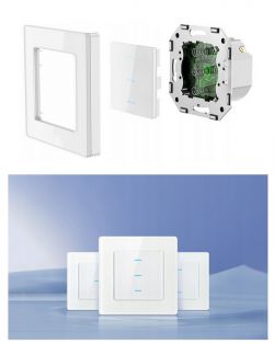
What we get in practice:
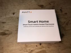
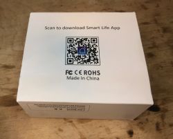
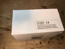
It seems that the importer tried to print his own print on the carton cover, and the carton is already without the Avatto name, typical:
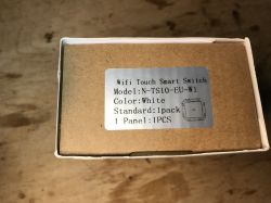
Full name: N-TS10-EU-W1
Instruction:
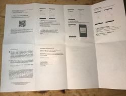
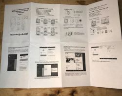
However, the instructions are in Polish, not bad, someone made an effort.
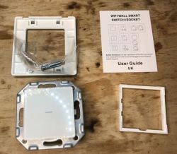
Set contents:
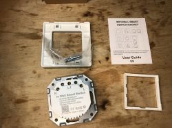
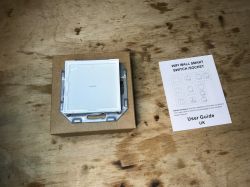
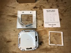
The set also includes a second manual, already in English:


Mounting screws are present.
Interior of Avatto N-TS10-W1
We release four catches:
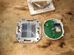
There is a CB3S module with BK7231 inside, you can load OpenBeken.
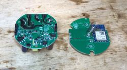
The board with the power supply is typical, the system powers DP2525, this board also has a 3.3V AMS1117 LDO, because the power supply itself generates 5V for the relay.
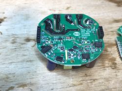
One row of connectors on the side is for mechanical support only, the other provides a connection to the front board.
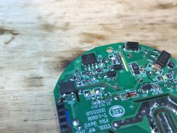
On the other side you can see a relay for the mentioned 5V and a nice accent is also a varistor, manufacturers do not always provide it, there is a fuse resistor as usual.
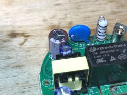
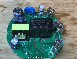
I also see room for additional relays.
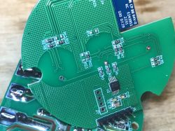
Another front plate, touch buttons support BA04T1:
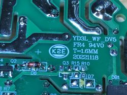
PCB designation YD3L_WF_DV5 20221118:
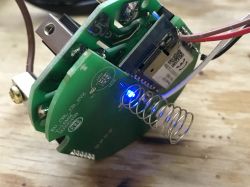
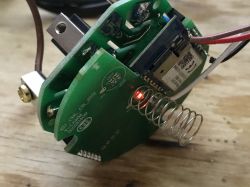
After connecting the power supply, we see that we have two colors of the LED:
Avatto N-TS10-W1 firmware change
Now let`s try to load OpenBeken to free this switch from the cloud.
For previous products in this series, the process was quite simple:
[CB3S/BK7231N] AVATTO TS02-EU-W3 light switch (triple version)
I also wanted to repeat it here, according to the flasher`s instructions:
https://github.com/openshwprojects/BK7231GUIFlashTool
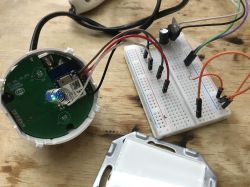
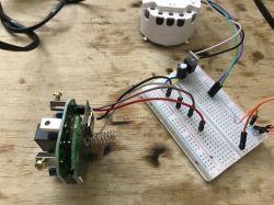
Just see the CB3S pins on the Tuya website and connect the USB to UART converter to TX1/RX1 and connect the 3.3V power supply:
https://developer.tuya.com/en/docs/iot/cb3s?id=Kai94mec0s076
It was possible to upload the batch, but this time it was not possible to read the GPIO configuration/template from Tuya.
In such a situation, use the GPIO Doctor tool located in the Web App:
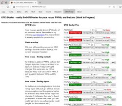
We examine each pin in turn:
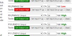
However, the result disappointed me a bit. We only have 3 GPIOs to control here:
- P8 - has a relay and both LEDs, blue and red, depending on whether the state is high or low
- P26 - green led, e.g. for WiFi
- P10 - button (touch button)
OBK template:
Code: JSON
Template import instructions can be found on the Elektroda.com YouTube channel:
Summary
Changing the firmware was quite easy. The template could not be generated automatically, but I created it for you manually. However, I don`t like the fact that the diodes indicating the relay status are on the same GPIO as the relay, so they cannot be easily disconnected, modifying the software will not help, you would have to operate on the PCB. In addition - no complaints, you can easily modify this product and pair it later, among others. With Home Assistant .
Cool? Ranking DIY Helpful post? Buy me a coffee.


