logo elektroda
logo elektroda
X
logo elektroda

Solderless conversion board for CB2S/WB2S Tuya modules compatible with ESP12 boards

p.kaczmarek2 3147 21
ADVERTISEMENT
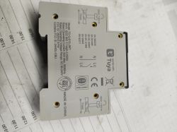
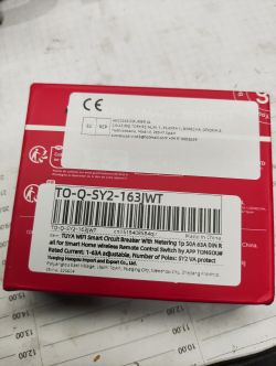
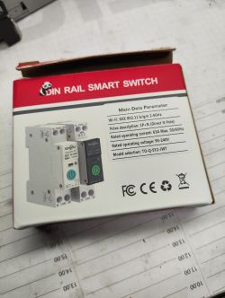
  • CB2S module mounted on a PCB held in a hand
    Solderless adapters for boards like ESP12/TYWE3S seem to be widely available, but we haven't seen any for devices in TYWE2S/ESP-02S form. That's why we've designed our own WB2S/CB2S to CB3S/WB3S form converter that can be used alongside the commercial modules. Our converter has been tested with new Tuya BK7231N "standing" modules and can be used to flash them effectively before soldering.

    So, let us consider the WB2S module:
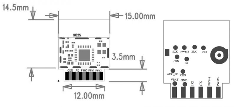
    Diagram and dimensions of WB2S module and converter board
    Pin No.SymbolI/O typeFunction
    1VBATPPower supply pin (3.3 V), which is connected to the VBAT pin on the internal IC
    2PWM2I/OCommon GPIO, which is connected to the P8 pin on the internal IC
    3GNDPPower supply reference ground pin
    4PWM1I/OCommon GPIO, which is connected to the P7 pin on the internal IC
    51RXI/OUART1_RXD, which is used as a user-side serial interface pin and is connected to the P10 pin on the internal IC
    6PWM0I/OCommon GPIO, which is connected to the P6 pin on the internal IC
    71TXI/OUART1_TXD, which is used as a user-side serial interface pin and is connected to the P11 pin on the internal IC
    8ADAIADC pin, which is connected to the P23 pin on the internal IC
    9PWM4I/OCommon GPIO, which is connected to the P24 pin on the internal IC
    10CENILow-level reset, high-level active (internally pulled high) Docking IC-CEN
    11PWM5I/OCommon GPIO, which is connected to the P26 pin on the internal IC

    For more information on this module itself (or BK7231), see:
    https://www.elektroda.com/rtvforum/topic3951016.html
    This module has the same chip as WB3S, but there are no solderless boards for that form. For WB3S, we could have used that board:
    https://www.elektroda.com/rtvforum/topic4010939.html
    The same board linked above can handle TYWE3S/ESP12 as well, but CB2S/WB2S form doesn't fit...

    That's why we've searched for suitable connector to make a conversion/daughter board ourselves. Here's what we found:
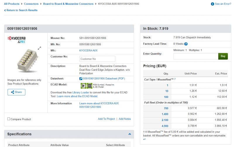
    Screenshot of an online store page displaying the KYOCERA AVX connector with part number 009159012651906.
    009159012651906 by KYOCERA AVX seems to have a matching pitch and contacts number. The current ratings are also of course well enough for our application:
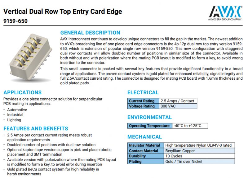
    AVX 9159-650 dual row top entry card edge connector.
    Here are dimensions of 4p version (6p is similiar):
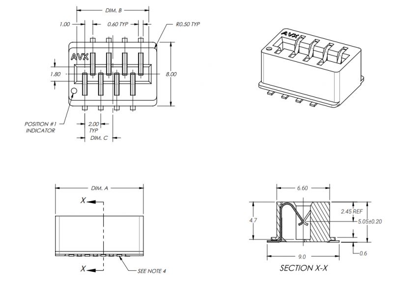
    Technical drawing of a KYOCERA AVX 4p connector
    So, after a moment in Kicad:
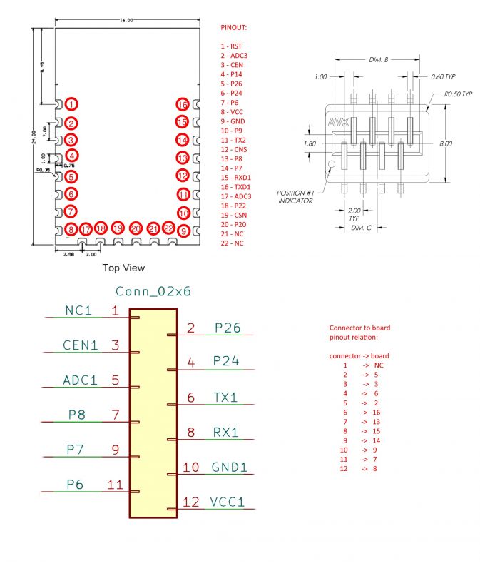
    Diagram and layout of the adapter board for CB2S/WB2S module.
    Note that first pin is NC (not connected) and that the board orientation matters.
    And the board:
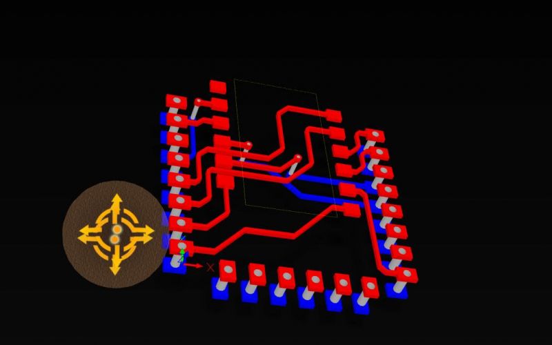
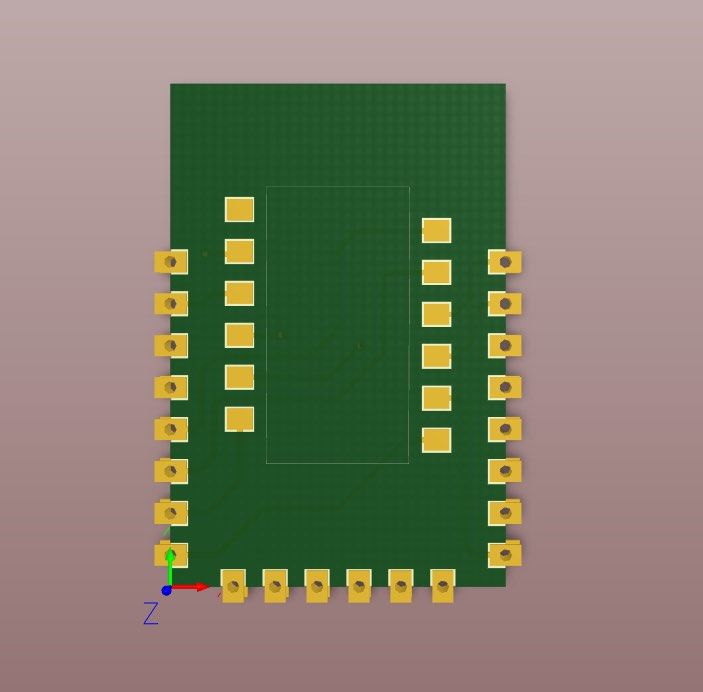
    PCB with red and blue traces in a 3D visualization.
    PCB design with pins on the edges
    We've ordered the boards and now's the time for testing:
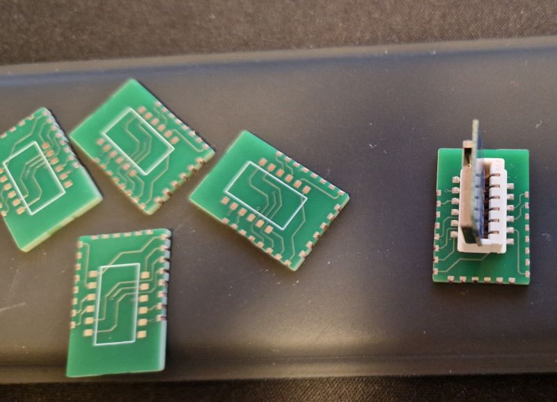
    Green printed circuit boards with a module mounted on one of them.
    CB2S fits well, and the daughter board fits TYWE3S/etc flasher good as well:
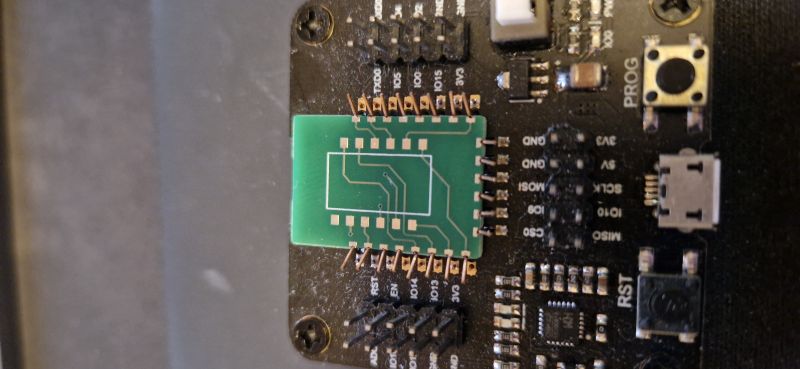
    Converter board on a main board without soldering
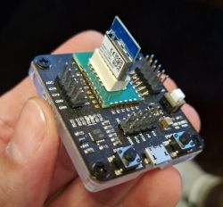
    The CB2S/WB2S is now easily flashable without soldering:
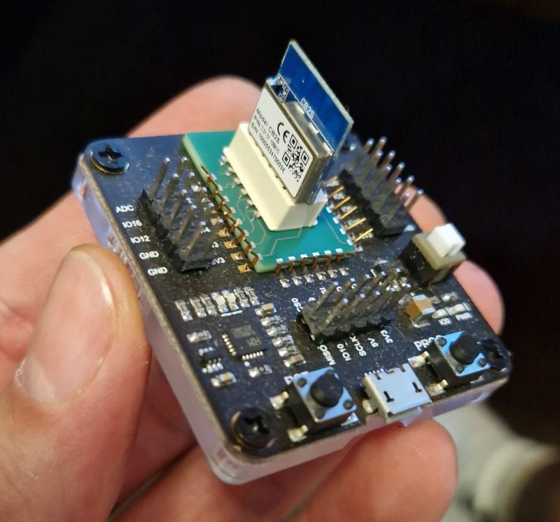
    CB2S module mounted on a PCB held in a hand
    Our flasher detects and flashes it well:
    https://github.com/openshwprojects/BK7231GUIFlashTool
    We may use it to flash our batch of WB2S/CB2S shown here:
    https://www.elektroda.com/rtvforum/topic4059644.html#21117913

    The following board could be easily used for a small scale production, because no soldering is needed to flash CB2S/WB2S with it.

    We're also planning to add ESP module support, but that will require adding few more resistors on the board itself - we have to consider the requirements first. Maybe we'll also find some space for a test LED...

    Ok, that's all for now. I'm attaching Kicad sources of our board. Stay tuned for more updates!

    PS: This project was realized with @DeDaMrAz . Thank you for our fruitful cooperation!

    Cool? Ranking DIY
    Helpful post? Buy me a coffee.
    About Author
    p.kaczmarek2
    Moderator Smart Home
    Offline 
    p.kaczmarek2 wrote 11983 posts with rating 10009, helped 573 times. Been with us since 2014 year.
  • ADVERTISEMENT
  • #2 21217331
    ferbulous
    Level 18  
    Hi, any plans for cbu?
  • #3 21217749
    p.kaczmarek2
    Moderator Smart Home
    That's an interesting idea. Do you think that CBU is popular enough to justify it? Isn't it BK7231N-only module? Or is there also a... WBU, with BK7231T?
    Helpful post? Buy me a coffee.
  • #4 21217829
    insmod
    Level 24  
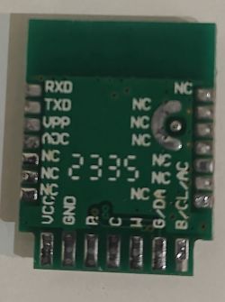
    CBU will only have 5 pins available, if connected vertically through a similar 7p adapter. But, it won't be possible to flash the board, since the uart pins are on the side. And it won't be possible to make an adapter, where cbu is placed horizontally, as its width it the same as that of an ESP-12 type module.
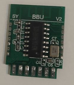
    Also, never seen before bluetooth BBU module (AK801?). Found in a random E27 bulb.
    Spoiler:

    BBU module with SY and V2 markings and electronic components, including an integrated circuit and capacitors. Electronic module with pin labels RXD, TXD, VPP, VCC, GND, and several NC.
  • ADVERTISEMENT
  • #5 21217866
    ferbulous
    Level 18  
    It’s more common to find CBU than CB2S/wb2s at least from the devices I’ve bought. Haven’t seen WBU yet
  • #6 21217898
    p.kaczmarek2
    Moderator Smart Home
    @insmod have you tried swapping it to WiFi module?

    What kind of devices do you buy @ferbulous ? For me, CBU is still very rare. I got CB2S/CB3S almost all the time.
    Helpful post? Buy me a coffee.
  • #7 21217986
    madamsz1
    Level 41  
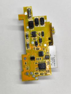
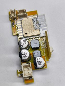
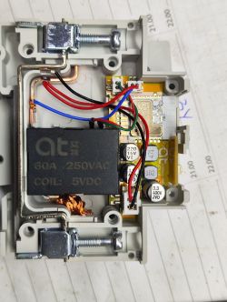
    I recently bought such a relay with measurement on the CBU:
    Close-up view of a circuit board with various electronic components. Electronic module with a relay and capacitors on a PCB. Image of the inside of a relay marked at 60A 250VAC COIL: 5VDC with visible wires and electronic components. Measurement relay on graph paper background. Packaging of a TUYA smart circuit breaker with metering, model TO-Q-SY2-163JWT. Photo of a DIN Rail Smart Switch box with technical data. Photo of a DIN Rail Smart Switch box with technical data. .
    By the way what pin-pin from esp8266 or esp32-c3 , esp32-s2, esp32-s3 or esp8285 will fit in this place ? He wants to Supla on this. I don't know how it will be with the measurement handling because there is something different (circuit) than in the GG but I will see what comes out.
  • #8 21218005
    p.kaczmarek2
    Moderator Smart Home
    I see a TO-Q-SY2-163JWT relay. What kind of circuit is there? BL0942? Probably in SPI mode? OpenBeken supports it.

    As for the swap:
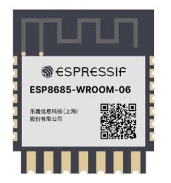
    ESP8685-WROOM-06 module by Espressif with visible logo and model number. .
    ESP8685-WROOM-06 fits in place of AXYU, BPU, CBU, ZSU, ZTU, WBRU.
    ESP8685-WROOM-06-H4 with 4MB flash (recommended) and ESP8685-WROOM-06-H2 with 2MB flash (not recommended, not enough flash)
    ESP8685-WROOM-06 module displayed on a product page with price and discount. .
    Helpful post? Buy me a coffee.
  • ADVERTISEMENT
  • #9 21217984
    divadiow
    Level 34  
    p.kaczmarek2 wrote:
    CBU is still very rare

    :o I think I have more CBUs than anything else. Probably because the door/window/flood devices seem to come with them and I bought too many looking for specific modules. Then of course in the LED SPI devices.

    Added after 52 [minutes]:

    excellent efforts on the adaptor btw
  • #10 21218078
    p.kaczmarek2
    Moderator Smart Home
    Well. most of the CB3S/CB2S form modules I see are in switch devices. "DIY smart switch", etc. I don't buy neither convert door/window/flood devices that often, as they are pain to handle.

    Futhermore, I have some donated CB2S/WB2S modules, probably only because it's easier for beginners to desolder CB2S/WB2S form than a, let's say, CB3S/WB3S one.

    I've even had to hack CB2S to get SPI out:
    https://www.elektroda.com/rtvforum/topic4005865.html

    Anyway, since you say you have many CBUs, maybe we can think about some CBU-based project? I don't know, buy some WS2812B strips, arrange them into 10x10 "screen" and try to display some graphics? We've already done something more or less similiar with @DeDaMrAz : https://www.elektroda.com/rtvforum/topic4054134.html
    Helpful post? Buy me a coffee.
  • #11 21218128
    madamsz1
    Level 41  
    p.kaczmarek2 wrote:
    What is the layout there? BL0942? Probably in SPI mode?
    .
    Yes exactly BL0942

    I have some ESP8684-WROOM-06C-H4 I used to order different ones for a few pieces each :) and this is what I ended up with.
  • ADVERTISEMENT
  • #12 21218133
    p.kaczmarek2
    Moderator Smart Home
    In that case, is that BL0942 there in SPI or UART mode?
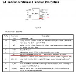
    Check the SEL pin:
    Pin configuration and function table for the BL0942 chip with SEL pin highlighted. .
    Helpful post? Buy me a coffee.
  • #13 21218147
    madamsz1
    Level 41  
    Hym... it looks like pin 7 is not connected to anything . So it kind of works in the UART
  • #14 21218160
    p.kaczmarek2
    Moderator Smart Home
    The question now is whether the Supla supports the BL0942 in UART mode?
    https://github.com/search?q=org%3ASUPLA%20bl0942&type=code
    I haven't found anything so far, but maybe I don't know how to look. And if it doesn't support.... well I might consider it, they are open source so maybe they would accept a PR from me if I could get it to work.
    Helpful post? Buy me a coffee.
  • #15 21218175
    madamsz1
    Level 41  
    The GUI is taken care of by Krycha and he is often open to suggestions, and sometimes if he has time I think people have made softys with support for something that is not in GG. I won't do it myself, I don't know and can't program :( . I'll also drop a topic on the forum and see what comes out.
  • #16 21218251
    insmod
    Level 24  
    >>21217898 Swapped it for an ESP8684-WROOM-06C-H2. Bulb looked like it worked all right, but as soon as i set the light to 100%, it rebooted. Had to reduce the cw max_power to 0.95.
  • #17 21218501
    p.kaczmarek2
    Moderator Smart Home
    @madamsz1 BL0942 is simple to use over the UART. The following topic describes in detail how I implemented its protocol in OBK:
    Electrical socket with LSPA9 energy measurement - we program our own firmware .
    Helpful post? Buy me a coffee.
  • #18 21218845
    ferbulous
    Level 18  
    >>21218128

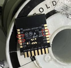
    Do take note some of the pins are NC so you might have to bridge to other unused pins if the required pins are on those pads
    ESP8266 board with highlighted pins against a white rotor background.
  • #19 21223339
    DeDaMrAz
    Level 19  
    Thanks @ferbulous for the picture, this actually gives me hope that we can find CBU like adapter board as well so the hunt begins ;)
  • #20 21238828
    ferbulous
    Level 18  
    DeDaMrAz wrote:
    Thanks @ferbulous for the picture, this actually gives me hope that we can find CBU like adapter board as well so the hunt begins ;)


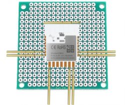
    You can still make your own diy CBU adapter with some prototype pcb and pogo pins soldered on the surface. Then just use clips to the uart
    Don't have it with me now but it looks like this

    Prototype circuit board with soldered CBU module and pogo pins.
  • #21 21276911
    antongarcias
    Level 1  
    May I have or order a couple of them (pre-soldered or only connector+circuit) ?
    Have you considered to make it available for people without having to order the items one by one ?¿
    Tx
  • #22 21279515
    ferbulous
    Level 18  
    Is there a suitable connector for the bottom 7 pin cbu?

Topic summary

The discussion revolves around the development of a solderless conversion board for CB2S/WB2S Tuya modules, compatible with ESP12 boards. Users express interest in the availability of adapters for various module types, particularly the CBU and CB2S/WB2S. The conversation highlights the challenges of flashing certain modules due to pin configurations and the rarity of specific module types. Participants share insights on the use of different ESP models, including ESP8684 and ESP8685, and discuss the implementation of protocols for energy measurement modules like the BL0942. Suggestions for DIY adapter solutions using prototype PCBs and pogo pins are also mentioned.
Summary generated by the language model.
ADVERTISEMENT