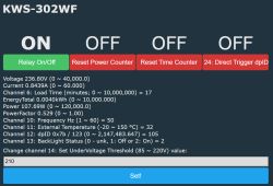
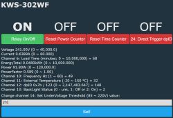
This is my first post in the forum, so apologize if something is out of the rules.
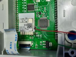
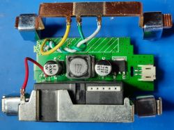
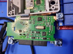
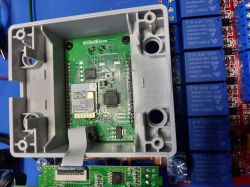
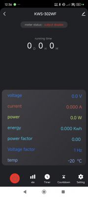
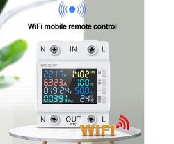
Recently I bought one Power Meter KWS-302WF and didn't like the way it used to current measuring. So I dismantled the device to see if I'm able to change from shunt to transformer.
This is the beginning of the story.
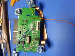
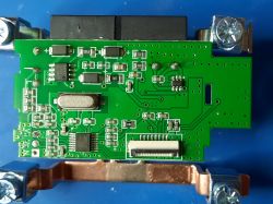
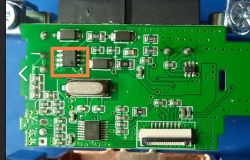
I saw the measuring chip is an HT7017 from HitrendTech, which is handled by a PY32F002A, by it turn gives the commands to a TM1622 which handles the display.
The WiFi chip is a CBU (BK7231N ?) connected to PY32F.
I made some soldering work and intercepted the communications between the CBU and the PY32F (and also between this one and the HT7017).
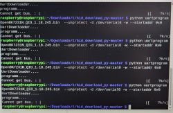
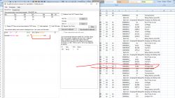
Following there are some photos and some files with the comm data.
Let see if this will be useful to change the firmware in the CBU ...
This xlsx file is a very good and professional job. You've done it very well. It can certainly help. Your doc may seem to be missing the dpIDs, but I think you can use this tool for that:
See: https://www.elektroda.com/rtvforum/topic3970199.html
Remember that you may need to sever UART connection in order to flash the device, because the same UART port which is used for flashing is also used for TuyaMCU communications.
Regarding shunt change - this may be very hard because PY32F002A is in charge of most of the stuff. You would need to somehow change the firmware of PY32F002A I guess. PY32F002A is already reporting measurements to the WiFi module via UART, so I don't think you can apply shunt change on WiFi module. But you probably already know that...
TM1622 is also very interesting for me, but again, in this case, TM1622 is handled by PY32F002A so you shouldn't worry about that. We're always changing just firmware of the WiFi module, not of the MCU. Still, OBK can already driver TM1650 and TM1637/TM1638 and similiar directly, so if there is a need, I could also get somehow a TM1622 driver working as well.
Is your goal just a firmware change or do you also want to change that shunt?
This xlsx file is a very good and professional job. You've done it very well. It can certainly help. Your doc may seem to be missing the dpIDs, but I think you can use this tool for that:
Thanks for the cumpliment ... I've not lost the dpID, I deleted it .. I explain why, I'm new in this stuff of HA and giving the first steps, so it is my "feeling" that this ID can be used to Tuya block my device ... sorry if this is a big mistake.
I will read your suggested hints ..
p.kaczmarek2 wrote:
Was this captured at 9600 baud or 115200?
The communication between HT7017 and the PY32F is 4800 bps. The communication between CBU and the PY32F is 115200 bps
p.kaczmarek2 wrote:
Remember that you may need to sever UART connection in order to flash the device, because the same UART port which is used for flashing is also used for TuyaMCU communications.
In order to flash the CBU, I'll take it out, it is only used as a kind of gateway and there are only 4 pins to be desoldered.
p.kaczmarek2 wrote:
Is your goal just a firmware change or do you also want to change that shunt?
This will be the hard part ... most probably I'll not succeed in reading the PY32F ... the chip probably is protected and only allowed programming. More .. there are few documents about HT7017 .. anyway I'm reading...
I explain why, I'm new in this stuff of HA and giving the firsts steps, so it is my "feeling" that this ID can be used to Tuya block my device ... sorry if this is a big mistake.
Impossible. Once you flash OpenBeken, Tuya has no access at all.
Lusant wrote:
The communication between HT7017 and the PY32F is 4800 bps.
The communication between CBU and the PY32F is 115200 bps
By TuyaMCU communication we mean between WiFi module and MCU, so 115200. You will need to include it into your autoexec.bat . I hope you can read a bit more about autoexec.bat in the TuyaMCU guide I mentioned.
Lusant wrote:
This will be the hard part ... most probably I'll not succed in reading the PY32F ... the chip probably is protected and only allowed programming.
More .. there are few documents about HT7017 .. anyway I'm reading...
Why do you want to change shunt?
There was something like:
https://github.com/no2chem/open-tuyamcu but I still think it would require lots of work. PY32F handles the MCU side of TuyaMCU communication, so by flashing it you'll already lose that.
The best and fast way to get support is to open a thread with that subject.
This is the noble purpose of Forums, people with doubts, ask, people who know, answer ...
In this way everyone can participate and learn.
Note: I've some documents and also some recorded sessions of serial comm between HT7017 and PY32F that I can publish if you want, anyway, there is a lot to learn about that chip because the documentation is not very detailed.
Hi @erbharatrankawat01,
Note: I've some documents and also some recorded sessions of serial comm between HT7017 and PY32F that I can publish if you want, anyway, there is a lot to learn about that chip because the documentation is not very detailed.
Hi, Lusant,
I have the same device with the same cbu and mcu. I would like to ask if you already flashed openbeken on it. And if so can you help me with the autoexec.bat file config. Thanks in advance.
I didn't do it yet. I already have made the backup using the tool made by @p.kaczmarek2 and also get some more data about the communication between the PY32F and the BK7231N. Meantime, I've read a bit more of Tuya and there is something about local address that I want to test. As I'm not sure if I can go back after flashing it, I suspend the project until I have time to restart.
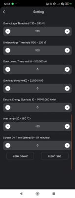
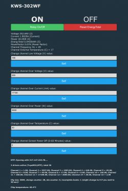
>>21348886 Yes I can control the relay, and the voltage is shown properly as shown in the device screen. Help me with OVP OPP and other configurable parameter settings.
Thank you for this project.
I’d like to report that the parsing of the frequency value is incomplete, as it is missing the decimal part.
Info:TuyaMCU:Received: 55 AA 03 07 00 08 6B 02 00 04 00 00 00 32 B4
Info:TuyaMCU:ProcessIncoming[v=3]: cmd 7 (State) len 15
Info:TuyaMCU:ParseState: id 107 type 2-val len 4
Info:TuyaMCU:ParseState: int32 50
As far as I can tell:
32 = 50
B4 = 180
In this case, the decimal point is the "0" from 180, so the correct value should be 50.0Hz.
Another example:
Info:TuyaMCU:Received: 55 AA 03 07 00 08 6B 02 00 04 00 00 00 31 B3
Info:TuyaMCU:ProcessIncoming[v=3]: cmd 7 (State) len 15
Info:TuyaMCU:ParseState: id 107 type 2-val len 4
Info:TuyaMCU:ParseState: int32 49
Here:
31 = 49
B3 = 179 = 9
This corresponds to 49.9Hz.
So the first number in decimal form from right to left is the missing decimal number.
Thank you for looking into this!
Another observation is that OpenBK is missing a "push button" option. We currently only have a toggle, whereas some functions are a simple "press to clear" type of action. In my autoexec.bat it would be used for setChannelType 9. Is this possible to implement somehow?
I've created a more comprehensive autoexec.bat for this device:
Hello, In my case the Wi-Fi stopped working and then the screen went out. On opening it up there is a faulty component - what is it and can it be purchased?
Thank you for sharing with the world all of your tests, results and tools I also have this device and want to make it better - it lacks at least the recovery time for Power On (this one should first disconnect the load at Power On, as it uses a latching relay, check the Voltage and only if it's in the configured range, command the relay to have the circuit closed), Under Voltage and Over Voltage.
Here is my "contribution back":
I had mine with MCU (PY32F002A) firmware version 0.1.17 (I think) and I saw that there is a newer version - 0.2.1.
Before upgrading MCU firmware I connected a RS232 serial adapter to the serial communication between MCU and CBU to sniff the firmware download.
Unfortunately I let it connected to RX line from the MCU to CBU.. so I only got the MCU answers to the CBU during the FW upgrade process.
But, using this websites: Link and Link I quickly understood the communication between CBU and MCU and I built a Python script to emulate the MCU communication part.
From what I could understand from sniffing the communication between CBU and MCU, CBU asks MCU only at boot about MCU firmware version (first I tried to send the modified product information during the normal operation of the device, without disconnecting CBU from MCU).
Briefly, this communication looks like this:
#Heartbeat check (0x00)
#CBU: 55AA 00 00 0000 FF
#MCU: 55AA 03 00 0001 00 03
#Query product information (0x01)
#CBU: 55AA 00 01 0000 00
#MCU: 55AA 03 01 002A 7B2270223A227461646D313361676A69676264747864222C2276223A22302E322E31222C226D223A327D 15
#Query working mode (0x02)
#CBU: 55AA 00 02 0000 01
#MCU: 55AA 03 02 0000 04
#Report network status (0x03)
#CBU: 55AA 00 03 0001 02 05
#MCU: 55AA 03 03 0000 05
# Some times there is another heartbeat check, but on this one, MCU answers slightly different - as this is not the first HB check
#CBU: 55AA 00 00 0000 FF
#MCU: 55AA 03 00 0001 01 04
#Query status (0x08)
#CBU: 55AA 00 08 0000 07
#MCU: answers with the known DIDs
#Start MCU OTA update (0x0A)
#CBU: 55AA 00 0A 0004 00002F0C 48 - this is for 0.2.1 MCU firmware version - it asks for buffer size and mentions that the bin file is of 0x2F0C size = 12.044bytes; also it mentions that the communication is going to take place using only 4 bytes for the offset bytes for the bin file
#MCU: 55AA 03 0A 0001 00 0D - MCU answers that the buffer size it accepts is of 256bytes (coded as a 0x00 - default, original old CBU fw version; 0x01 is 512bytes and 0x02 is 1024bytes)
#Transfer update package
#55AA 00 0B 0104 00000000 {xx} XX - {xx} are the bytes; 0104 means 0x100bytes = 256 bytes and 4 is for number of offset bytes; first 4 bytes and the offset
#55AA 03 0B 0000 0D - standard answer when everything is OK on the receiving packet
#Other CBU requests(?) seen during startups
#55AA 00 03 0001 03 06 - Network status changed
#55AA 00 03 0001 04 07 - Another network status changed
The MCU product information answer translates to this (simple HEX to ASCII conversion):
Uª*{"p":"tadm13agjigbdtxd","v":"0.2.1","m":2} = Header, type of answer, number of bytes, DATA, Checksum
It is enough to change from 0.2.1 to something lower and then update the checksum. In my test I did with 0.2.0:
#55AA 03 01 002A 7B2270223A227461646D313361676A69676264747864222C2276223A22302E322E30222C226D223A327D 14
With this I was able to emulate the device, still using the original CBU, to have it connect to Smart Life Cloud and download again the firmware for the MCU:
PY32F00...bin Download (11.76 kB) This firmware bin isn't all that is stored in the MCU, there seems to be other flash locations that are accessed by this firmware, locations that aren't contained in this dump (maybe the settings, that seem to be persistent during reboots) and there is also the Boot Loader that gets called during the update (you will see "boot" on the screen and also a counter (?) during the real firmware update), which seems to be in a dedicated flash space and it's written in the manufacturing plant, at least.
I didn't find any way of having the MCU exit this firmware process, but because I didn't wrote anything at that stage I simply rebooted the device (power off - power on) and it was OK.
I tried some decompilation of the firmware, using Ghidra, choosing ARM Cortex, Little Indian, code at 0x0000. You also need to load the same code at 0x0800 0000, as here is the Flash Address where it's stored, but at boot, depending on the settings, at 0x0000 you'll have either this Main Flash, System Flash (bootloader) or RAM. In normal operation, at 0x0000 you'll have Main Flash - the firmware we download.
MCU PY32F002A complete datasheet can be found here: Link I didn't try writing the dumped firmware to see if it is OK, but because it had the correct size, because I also found the same HEX bytes for the product information in it and also because Ghidra is able to use it (mostly in manual process of going to un-decompiled bytes and pressing F12 - decompile it as ThubCode) I guess it is OK
I'm just a hobbyist when it comes to programming, I hate Python, but for a quick scripting process on Windows (too lazy to power a Raspberry Pi with Linux and too much in a need for a faster process than doing tests with an ESP32 - takes too long to write the new code) it was good enough. It has some comments in it, it can be better, but for what I needed to do, I can say that it's good enough The script uses a transfer buffer size (window) of 1024 bytes, instead of the default one: 256bytes (and maybe the only working buffer size for the MCU), just to have it in less lines, to copy-paste them in an HEX editor (on Windows I prefer HxD), so I can manually rebuild the MCU firmware.
tryser_...txt Download (9.15 kB) (it is small enough not to hassle with Python to have it written to a file, but instead using the method described)
Now I just hope that someone on Elektroda decompile the firmware to something we can work with so we can add the needed changes.. or (even better?) use the code to have the CBU or an ESP32 for example talk directly with the measuring chip - HT7017, with the display driver - TM1622, and also read the 4 buttons, control the backlight and, of course, the status of the relay (latching type).
Yes, I know this is beyond this topic's main target, but if it goes to this kind of project, we can split the topic.
Thank you for this project.
I’d like to report that the parsing of the frequency value is incomplete, as it is missing the decimal part.
Info:TuyaMCU:Received: 55 AA 03 07 00 08 6B 02 00 04 00 00 00 32 B4
Info:TuyaMCU:ProcessIncoming[v=3]: cmd 7 (State) len 15
Info:TuyaMCU:ParseState: id 107 type 2-val len 4
Info:TuyaMCU:ParseState: int32 50
As far as I can tell:
32 = 50
B4 = 180
In this case, the decimal point is the "0" from 180, so the correct value should be 50.0Hz.
Another example:
Info:TuyaMCU:Received: 55 AA 03 07 00 08 6B 02 00 04 00 00 00 31 B3
Info:TuyaMCU:ProcessIncoming[v=3]: cmd 7 (State) len 15
Info:TuyaMCU:ParseState: id 107 type 2-val len 4
Info:TuyaMCU:ParseState: int32 49
Here:
31 = 49
B3 = 179 = 9
This corresponds to 49.9Hz.
So the first number in decimal form from right to left is the missing decimal number.
Thank you for looking into this!
....
Hi adolfotregosa,
at first sight, I agreed with you, but having a closer look, I saw that you were misled by the last byte which is a checksum byte, not a "data" byte.
55AA 03 07 0008 6B02000400000032B4 translates to: Header, Communication Version, Command / Type of answer, Number of Data Bytes, DATA, Checksum
Changing any byte before the Checksum one, will change the Checksum Checksum is the remainder of the division between the sum of all the bytes (before the checksum one) and 0x100 (256)
So in your example:
55 AA 03 07 08 6B 02 04 32 = 1B4
0x1B4 % 0x100 = 0xB4
(% is the sign usually used in programming = modulo operator; in math is written as "mod")
I'll sniff some more the communication between CBU and MCU to see where this decimal is sent.
Added after 2 [minutes]:
divadiow wrote:
thanks. interesting. Lusant's backup is v2.1.6 which now has a Cloucutter profile. Yours is 2.1.17 which is a known patched version.
I have the same FW version. I compared the bin files and the difference starts at 0x1CF000 - where the encrypted config starts.
His config is with Tuya, mine is with SmartLife.
Should we delete his bin dump as anyone with BK7231GUIFlashTool can decode his encrypted data? (for example I saw his WiFi SSID and password - not that important as the SSID name suggests: he was using HotSpot function from his Android phone, but maybe there is other real sensitive data).
Why doesn't BK7231GUIFlashTool decode the dpIDs from this config?
Looking into the decoded bin files from DebugAES folder I saw that they do appear in a JSON format, but a malformed one - missing the beginning or the end of it, but as it is written several times, it can be reconstructed.
All it could "decode" is: { "baud":"115200" }
I've used the JSON extracted from the original firmware (divadiow added it first to this topic) to try to describe as best as I could the values.
Still, there are 4 dpID that I couldn't figure what are used for / how are used:
0x7b / 123 which can have a ReadOnly value between 0 and 2,147,483.647 (= 0x7FFF FFFF) = "Add Electricity" according to divadiow
At the beginning, it had a value of 21; after hooking a big load (refrigerator) it started to grow. Resetting values, unplugging power or the load, didn't make it go back to that low value.
Later Edit: this dpID stores the counter for Total Energy measured by the device since it was first used. The value can only be reset by holding + and - buttons on the device for 5s. THIS WILL RESET MCU to factory settings - you'll have default values for UnderVoltate, OverVoltage, OverTemperature and so on.
dpID 0x70 / 112 which can have a Write value between 0 and 60,000, and according to the JSON, it should be configured with a step of 30 = "Poweroff Time" according to divadiow
I've tried with many values, I didn't spot any change. Upon CBU reboot, this value goes back to 0.
dpID 0x75 / 117 "can" (according to JSON) be set (write) to only 3 values: 0, 1 or 2 = "Power Down Memory" according to divadiow
Tested all of them. Nothing found. Upon CBU reboot, this value goes back to 0.
dpID 0x7a / 112 is described as being "boolean" in JSON and also has the "trigger": "direct" tag, which is unique - it is configured only for this dpID in JSON.
= "Switch" according to divadiow
Using it as an On/OFF button I see it commands the Relay which is also controlled by dpID 0x10 / 16. The MCU responds back with updated status for dpID 0x10.
Later Edit: This is used by the original app - in Smart Life you can create a schedule to control the Relay Status. Probably they wanted to use a different dpID for this command, to know, maybe, which process changed the relay status (last one).
We really miss a new button type - one that doesn't change it's status (from Off to On / from Red to Green) for commands that are needed only with a value of 1, to trigger something, when the MCU won't update the status of those dpIDs, case in which the toggle button isn't good as it modifies the value that is going to send on next press, from 1 to 0, because now it thinks it's On and wants to make it Off on next press. This button can change it's color, at press time, but as soon as it isn't pressed anymore, it should get back to it's "Off" color.
The 2 command that need this kind of button are:
dpID 0x76 / 118 "Reset Power Counter"
dpID 0x78 / 120 "Reset Time Counter"
0x7b / 123 which can have a ReadOnly value between 0 and 2,147,483.647 (= 0x7FFF FFFF) = "Add Electricity" according to divadiow
At the beginning, it had a value of 21; after hooking a big load (refrigerator) it started to grow. Resetting values, unplugging power or the load, didn't make it go back to that low value.
Such I remember, this one is the Running Time counter.This is wrong
Also, I've found the attached text file (don't know where). With a smartphone and Google Translator from Pictures, you can find out what is the text in Mandarin.
Regards.
EDIT: Opps .. it's Energy Totalizer .. I think there is a second Totalizer which is only resetable with the buttons in the device (hold buttons + and - for 5 sec)
The discussion centers on modifying the Power Meter KWS-302WF to switch its current measurement method from a shunt resistor to a transformer. The device uses an HT7017 measurement chip from HitrendTech, controlled by a PY32F002A MCU, which interfaces with a TM1622 display driver and a WiFi module identified as CBU (likely BK7231N). Communication between HT7017 and PY32F occurs at 4800 bps, while between CBU and PY32F it is at 115200 bps. Efforts include intercepting UART communications and backing up firmware to enable custom firmware flashing, particularly on the CBU WiFi module, using OpenBeken firmware and TuyaMCU protocols. Challenges include potential MCU protection and limited documentation on HT7017. The community provides resources such as firmware backups, dpID mappings, and autoexec.bat configuration examples for TuyaMCU integration, enabling relay control, voltage display, and parameter settings like overvoltage and overcurrent protection. Additional observations highlight incomplete frequency parsing in OpenBK firmware and the absence of recovery time settings after protection trips. A hardware fault involving the U3211 power supply chip is also discussed, with datasheets and sourcing advice provided. Summary generated by the language model.