 .
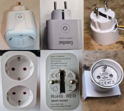
.Various types of plugs, modules and sockets that offer energy measurement and normally work with the manufacturer's cloud can be bought cheaply on the web. Here I will show how such a socket can be freed from the cloud and configured independently, including how events can be triggered when, for example, a given voltage value is exceeded, and how measurements can be visualised in the form of graphs held on the same device. This topic will not be about a specific device, but rather more generally about a group of devices manufactured in China and available for cheap purchase from portals with names often starting with 'A'....
Why change the firmware? .
Users give different reasons for wanting to change the firmware of a device, but these are usually driven by the desire to make the product cloud-free (off the manufacturer's servers), to avoid potential surveillance and problems when, for example, the manufacturer's cloud stops working and also the need to connect devices from different ecosystems. Once the firmware is changed to an open source solution, it is much easier to extend the functionality of a given product, additional sensors can be added to it, it can be freely programmed, it can be connected to the Home Assistant, etc.
Changing firmware .
For the ESP8266 and ESP32 series chips, I recommend uploading Tasmota according to the methods described earlier:
How to install Tasmota easily - online installer tasmota.github.io/install via web browser .
SmartLife switch - test, interior and programming a light switch on WiFi
ESP8266 and Tasmota - step by step WiFi relay control
Here, however, I will focus on circuits that can also be found in low-cost products, namely:
- BK7231T (WB3S, WB2S, WB2L, etc).
- BK7231N (CB2S, CB2L, WB2L_M1, etc)
- BK7231M , this is BK7231N with keys 00000000, sometimes designated as BL2028
- T34 (T34 is based on BK7231N)
- BL2028N (BL2028N is BK7231N manufactured by Belon)
- BL602 (SM-028_V1.3 etc), see also BL602 flash OBK via OTA tutorial (Magic Home devices only)
- LF686 (this is the BL602 version)
- W800 (W800-C400, WinnerMicro WiFi & Bluetooth), W801
- W600 (WinnerMicro chip), W601 (WIS600, ESP-01W, TW-02, TW-03, etc.)
- LN882H from Lightning Semi
- XR809 (XR3, etc)
I will upload OpenBeken multi-platforms to them, details here:
https://github.com/openshwprojects/OpenBK7231T_App
Documentation:
https://github.com/openshwprojects/OpenBK7231T_App/blob/main/docs/README.md
Script examples:
https://github.com/openshwprojects/OpenBK7231T_App/blob/main/docs/autoexecExamples.md
List of commands:
https://github.com/openshwprojects/OpenBK7231T_App/blob/main/docs/commands.md
The procedure for changing the firmware in each case requires a USB to UART converter:
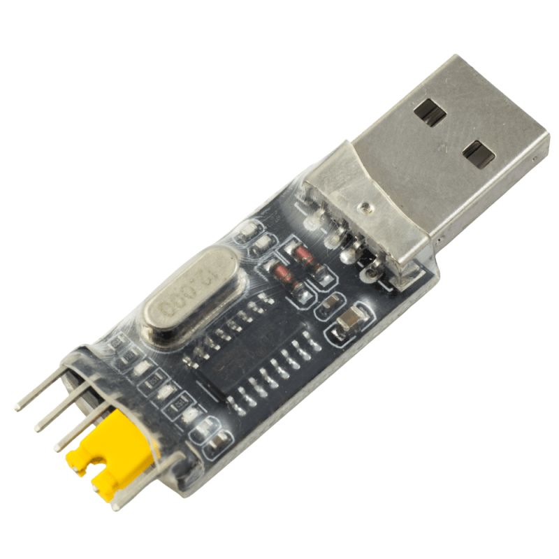 .
.I am using the CH340 version. For this you will need an external power supply with a 3.3V LDO. The power supply from the CH340 is not sufficient, it does not have the current capacity.
The procedure for flashing a given chip is found in one of three ways:
1. via the project's readme:
https://github.com/openshwprojects/OpenBK7231T_App
For the BK7231 we have the flasher here:
https://github.com/openshwprojects/BK7231GUIFlashTool
2. via our Youtube channel, there are instructions for BK7231, BL602, WX00:
https://www.youtube.com/@elektrodacom
3. via the device list (it is worth noting that we only want "Detailed entries", i.e. detailed descriptions)
https://openbekeniot.github.io/webapp/devicesList.html
Basic energy measurement .
Based on over 650 descriptions
of devices on our IoT list, I can say that the most common in this type of product are the BL0942 and BL0937 chips. The main difference between the two is that:
- BL0942 uses the UART (the same UART port as for programming the WiFi module), possibly occasionally SPI
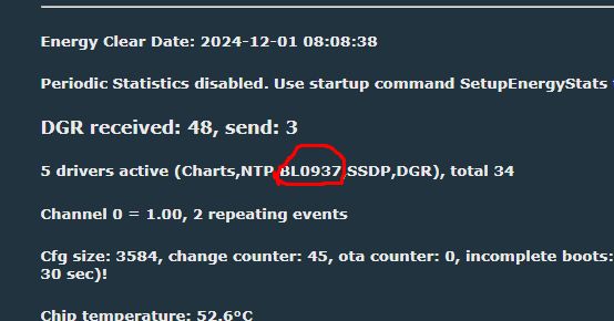
- BL0937 uses the CF, CF1 and SEL pins (the frequency of the pulses issued to a given pin determines the power, voltage or current)
For us, this means only one thing:
- in the case of BL0942, you do not even need to specify the pins, because it is known in 99% of cases that UART1 is used
- in the case of BL0937, you have to specify to which pins of the WiFi chip CF1, CF and SEL are connected.
In the case of BK7231 based devices our flasher will detect the pin roles itself:
Otherwise we have to analyse the PCB with a multimeter or look for a similar device in our list .
In the case of BL0942, in the firmware itself, we enter the command:
startDriver BL0942
e.g. in autoexec.bat , and in the case of BL0937 it is sufficient to set the corresponding pin roles. In both cases it is worth performing a reboot. We will find out from the web panel that the controller has booted:
 .
.Calibration of energy measurement .
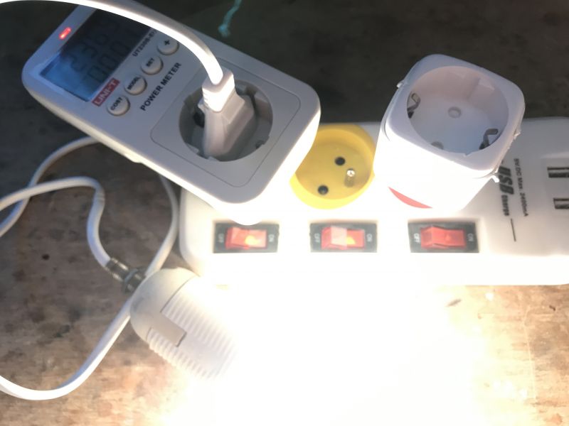
Calibration is done in a similar way to the Tasmot. We take a higher-end energy meter, connect a resistive load in the form of a 60W light bulb, measure the voltage, current and power on it, and then enter these values into our product (having that light bulb connected and lit at all times).
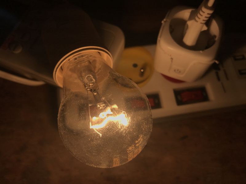
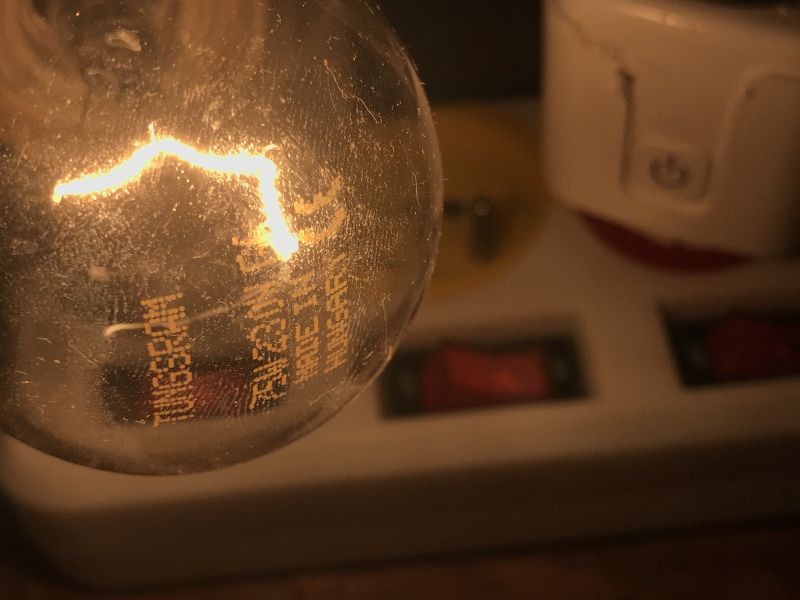 .
.The commands to enter are:
- VoltageSet 230
- PowerSet 60
- CurrentSet 0.236
You used to have to manually write the results, but now the firmware will remember this itself.
If you do not want to write commands, there is a form for this in the Web App under Tools:
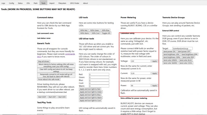 .
.This is what the device panel looks like after calibration:
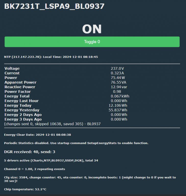 .
.Summarised energy measurement and consumption for the day (and more) is also available.
Events and automations .
The scripting language itself also supports simple automations. They are all done programmatically, so we won't realise an ultra-fast fuse or surge protection on this, but we can, for example, limit the power drawn from a device:
addChangeHandler Power > 50 POWER OFF
Result:
After a few seconds, the relay switched off.
We can also make a smarter power limiter, e.g. for the basement, which switches the relay back on after a short time:
addChangeHandler Power > 50 backlog POWER OFF; addRepeatingEvent 2 1 POWER ON
Result:
Sending measurements to HTTP server .
The firmware is also able to send a GET request with the contained measurements, which we can direct to our publicly available or locally accessible server. Such GET arguments can, for example, be processed in PHP and saved to a database or file.
Example script that writes the values of the v, c and p arguments from the GET to data.csv with the current time:
Code: PHP
This can be tested from within the browser:
http://192.168.0.213:8003/meas.php?v=233&c=0.44&p=75
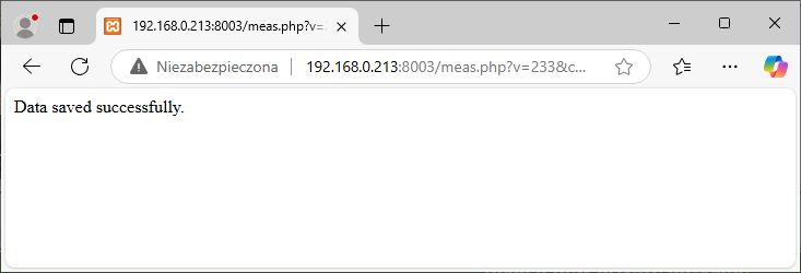 .
.As a check, this can also be called from the OBK command line. Ultimately from a script:
addRepeatingEvent 60 -1 SendGET http://192.168.0.213:8003/meas.php?v=$voltage&c=$current&p=$power
Example file content:
"2024-12-01 11:00:23",237.288681,0,0
"2024-12-01 11:00:24",238.197128,0,0
"2024-12-01 11:00:25",237.246231,0,0
"2024-12-01 11:00:26",237.433013,0,0
"2024-12-01 11:00:27",237.433013,0,0
"2024-12-01 11:00:28",237.577346,0,0
"2024-12-01 11:00:29",237.577346,0,0
"2024-12-01 11:00:30",237.144348,0,0
"2024-12-01 11:00:31",237.144348,0,0
"2024-12-01 11:00:32",237.144348,0,0
Integration with Tasmota Control .
OpenBeken provides basic compatibility with Tasmota's JSON format, so applications such as Tasmota Control will also work with such devices. All over the local network:
Integration with SSDP .
The multi-platform SSDP driver makes devices with OpenBeken visible by, for example, Windows computers:
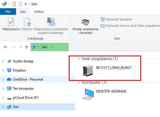 .
.Tutorial:
Charts Tutorial.
As documented in the charts:
Charts in OpenBeken - configurable measurement history hosted on IoT device .
I have created an autoexec.bat script:
startDriver charts
startDriver NTP
waitFor NTPState 1
// chart with max 100 samples, 3 variables and 3 separate vertical axes
// TODO: tune samples count
chart_create 100 3 3
// set variables along with their axes
chart_setVar 0 "Voltage" "axvolt"
chart_setVar 1 "Current" "axcurr"
chart_setVar 2 "Power" "axpower"
// setup axes
// axis_index, name, flags, label
chart_setAxis 0 "axvolt" 0 "Voltage (V)"
chart_setAxis 1 "axcurr" 1 "Current (A)"
chart_setAxis 2 "axpower" 2 "Power (W)"
// every 30 seconds, -1 means infinite repeats
// TODO: tune time here
addRepeatingEvent 30 -1 chart_addNow $voltage $current $power
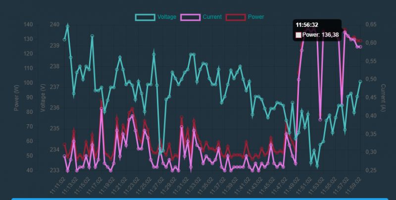
Example graph, you can see the voltage fluctuation and the moment the 75W bulb is switched on:
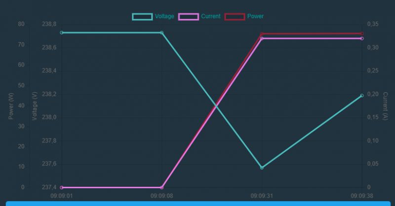
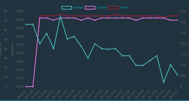 .
.And here's a tidbit - guess at what point I enabled the Stable Diffusion model to generate images on my laptop?
Grouping with other products over a LAN without a server .
OpenBeken supports Tasmota Device Groups , so outlets programmed in this way can be grouped, so that turning on one will make the others turn on with it, etc.. For lights similarly, even the RGB control can be synchronised:
Tasmota Device Groups - connection of OpenBeken (BK7231T/BK7231N) to Tasmota .
Induction switch controlling other devices from the home - Tasmota Device Groups .
Integration with Home Assistant .
A socket programmed in this way can be connected easily to the Home Assistant, and then all the automations from the HA also gain control over it. It can then be integrated into various other ecosystems.
Modifiability .
After changing the firmware, the chip's free GPIO from WiFi can be easily used - a temperature sensor or IR receiver, for example, can be connected:
And what about more complex devices? .
More complex energy measurement devices, often also offering an LCD display or measurement of several phases simultaneously, are usually based on the TuyaMCU:
TuyaMCU protocol - communication between microcontroller and WiFi module .
Flashing guide:
TuyaMCU flashing, installation and configuration guide - configure dpID for Home Assistant .
One example of how to convert such a device:
Advanced energy meter/thermostat with LCD Atorch S1TW-FR - cloudless operation .
Summary .
Most budget WiFi-based energy meters on the market can be reprogrammed using the method shown here. If you are looking for a specific model (to purchase or information about) then I invite you to our list of device templates:
https://openbekeniot.github.io/webapp/devicesList.html
If you have a product that is not yet on this list, feel free to post in the forum - we will help with the conversion, step by step.
Do you have any IoT devices to which you have changed or intend to change the firmware?
Cool? Ranking DIY Helpful post? Buy me a coffee.


