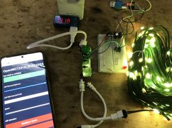
 .
.
A friend slipped me a rich festive set of individually addressable, colourful WS2812 LEDs for the Christmas tree. All controlled via WiFi, remote control and via buttons on the casing. Initially the friend wanted to use it with the Tuya app, but found that the app locks up on mode selection, so he gave me the task of reworking the whole thing to work with OpenBeken .
The kit already includes LEDs (20 metres, 200 pieces) and was bought for £150. The LEDs are IP67 rated.
Let's start with the packaging:
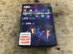
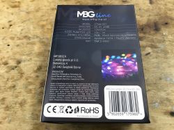 .
.
Model: CTree-001, MGB line LED lights CTree-001,20m.
Contents as expected:
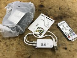 .
.
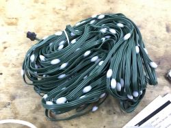 .
.
Instructions:
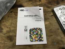
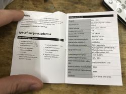
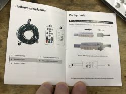
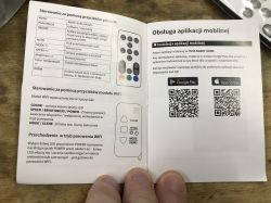
 .
.
The LEDs are IP67 waterproof:
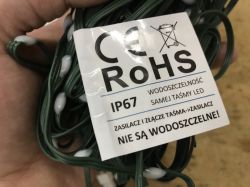 .
.
... but the controller is not.
Test with the Tuya app .
The test with the Tuya app is to see if the problem reported by the reader occurs. I paired according to the instructions. Apparently the colour selection works:
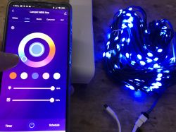
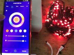
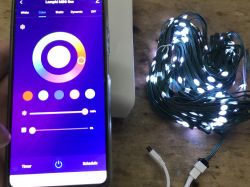 .
.
In full white mode the strip does not even draw much current:
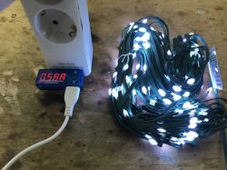 .
.
I was also able to switch to static animation (from what I understand, this is a single colour animation):
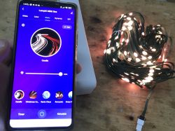 .
.
Playing with the colours in the video:
Then I wanted to switch to Dynamic/DIY, well that's where the app got stuck:
So the reader was right. It is not possible to enable animation from within the app. Here you even have to change the firmware.
Interior of CT001 .
Lift the cover:
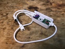 .
.
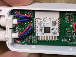
Inside is the CBU module, or BK7231N. You can upload OpenBeken .
 .
.
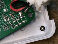
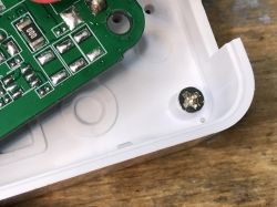
I was also curious about the plate assembly - the screw is.... under the plate:
 .
.
And right next to it you can see a small ball of binder. With finer circuits, such balls like to make an unexpected short circuit.
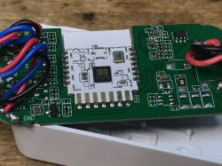
I removed all the electronics:
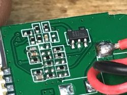 .
.
The circuit marked 621 D3278 is probably some sort of amplifier from a microphone, can anyone find its note?
There's a place for transistors on the board, meaning this board is also for PWM-based strips, probably for five-channel (RGBCW):
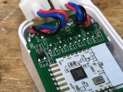 .
.
On the other side there are buttons, there is a 3.3V LDO, programming pads and a microphone:
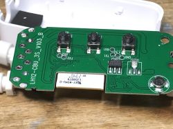
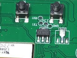
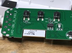
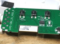
 .
.
Changing CT001 firmware .
As per our flasher's instructions:
https://github.com/openshwprojects/BK7231GUIFlashTool
You can also preview tutorials on our YT channel, e.g. for CB2S:
CBU pinout:
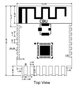 .
.
| Pin number | . Symbol | I/O type | Function | |||
| 1 | P14 | I/O | Common GPIO, which can be reused as SPI_SCK (Correspond to Pin 11 of the IC) | |||
| 2 | P16 | I/O | Common GPIO, which can be reused as SPI_MOSI (Correspond to Pin 12 of the IC) | |||
| 3 | P20 | I/O | Common GPIO (Correspond to Pin 20 of the IC) | |||
| 4 | P22 | I/O | Common GPIO (Correspond to Pin 18 of the IC) | |||
| 5 | ADC | I/O | ADC, which corresponds to P23 on the internal IC (Correspond to Pin 17 of the IC) | |||
| 6 | RX2 | I/O | UART_RX2, which corresponds to P1 on the internal IC. (Correspond to Pin 28 of the IC) | |||
| 7 | .TX2 | I/O | UART_TX2, which is used for outputting logs and corresponds to P0 of the internal IC (Correspond to Pin 29 of the IC) | |||
| 8 | P8 | I/O | Support hardware PWM (Correspond to Pin 24 of the IC) | |||
| 9 | P7 | P7 | I/O | Support hardware PWM (Correspond to Pin 23 of the IC) | ||
| 10 | P6 | I/O | Support hardware PWM (Correspond to Pin 22 of the IC) | |||
| 11 | P26 | I/O | Support hardware PWM (Correspond to Pin 15 of the IC) | |||
| 12 | 12P24 | I/O | Support hardware PWM (Correspond to Pin 16 of the IC) | |||
| 13 | GND | P | Power supply reference ground | |||
| 14 | 3V3 | P | P | Power supply 3V3 | ||
| 15 | TX1 | I/O | UART_TX1, which is used for transmitting user data and corresponds to Pin 27 of the IC. For the MCU solution, please refer to CBx Module. | |||
| 16 | .RX1 | I/O | UART_RX1, which is used for receiving user data and corresponds to Pin 26 of the IC. For the MCU solution, please refer to CBx Module. | |||
| 17 | . P28 | I/O | Common GPIO (Correspond to Pin 10 of the IC) | |||
| 18 | CEN | I/O | Reset pin, low active (internally pulled high), compatible with other modules (Correspond to Pin 21 of the IC) | |||
| 19 | >Reset pin, low active (internally pulled high). 19 | P9 | I/O | Common GPIO (Correspond to Pin 25 of the IC) | ||
| 20 | P17 | I/O | Common GPIO, which can be reused as SPI_MISO (Correspond to Pin 14 of the IC) | |||
| 21 | P15 | I/O | Common GPIO, which can be reused as SPI_CS (Correspond to Pin 13 of the IC) | |||
| Test point point | CSN | I/O | Mode selection pin. If it is connected to the ground before being powered on, enter the firmware test mode. If it is not connected or connected to VCC before being powered on, enter the firmware application mode. Correspond to Pin 19 on the internal IC. |
But I haven't even used it here, because there are pads after all....
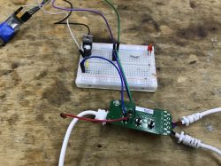
Flashing went smoothly, OpenBeken created its access point, where I entered my WiFi details .
Discovery of GPIO roles, buttons .
The WS2812 is definitely connected at P16 - this is the BK7231's hardware SPI output, which is used to control just these types of LEDs via DMA.
The microphone is on an ADC, or P23. This is the only ADC on the BK7231.
What remains is the location of the buttons. This is where GPIO Doctor can be used:
GPIODoctor in OpenBeken - a convenient way to learn about GPIO roles in an IoT device .
Results:
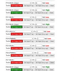 .
.
The question of the IR receiver remains. Here I used an ohmmeter. There was a resistance of 100 ohms from the IR to the corresponding pin.
ADVERTISEMENT
Script WS2812 .
A separate tutorial should be used here:
Animations OpenBeken WS2812B - new HTTP panel integration, PixelAnim driver .
This will provide us with a basic colour and animation system, but for now without buttons or remote control....
Here I only had to specify the colour format - GRB. Used autoexec.bat:
startDriver SM16703P
SM16703P_Init 200 GRB
startDriver PixelAnim
A brief demonstration of the operation:
Pilot scripting .
OpenBeken includes an IRRemote port, so it can support different remotes. You just need to know the correct codes. The received IR codes will appear in the Web app Log when you select the IRRecv pin role in the GPIO configuration and fully reboot:
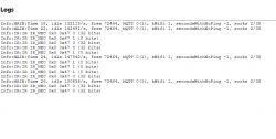 .
.
This is what it looks like live - I have the Web App log open and look at what codes are being received:
There is a similar presentation on our Youtube:
In the same way, you can also hook up another remote control to our device, even one from a TV, e.g. with RC5, RC6 coding, etc...
An example autoexec.bat with the scripted part of the IR events:
startDriver SM16703P
SM16703P_Init 200 GRB
startDriver PixelAnim

addEventHandler2 IR_NEC 0x0 0x47 POWER TOGGLE
addEventHandler2 IR_NEC 0x0 0x42 led_basecolor_rgb FF0000
addEventHandler2 IR_NEC 0x0 0x52 led_basecolor_rgb 00FF00
addEventHandler2 IR_NEC 0x0 0x4A led_basecolor_rgb 0000FF
addEventHandler2 IR_NEC 0x0 0x1C led_basecolor_rgb FFFFFF

addEventHandler2 IR_NEC 0x0 0xC add_dimmer 10
addEventHandler2 IR_NEC 0x0 0x8 add_dimmer -10Reminder of the command list:
https://github.com/openshwprojects/OpenBK7231T_App/blob/main/docs/commands.md
The remote control works (even at a rather awkward angle):
Button scripting .
There are two methods for this - either we assign them ready-made roles, e.g. Btn_NextColor, see the list of GPIO roles:
https://github.com/openshwprojects/OpenBK7231T_App/blob/main/docs/ioRoles.md
or we assign them the role Btn_ScriptOnly, and script them commands manually. You can then separately handle single click, double click, hold, etc. Search for "OnClick" in the documentation:
https://github.com/openshwprojects/OpenBK7231T_App/blob/main/docs/autoexecExamples.md
Final device template .
Autoexec.bat example already given, it's still time for the template:
Code: JSON
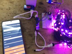
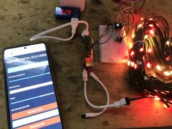
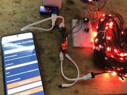
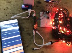
Current consumption at various effects .
It appears that a 1.5A power supply is sufficient for this product:
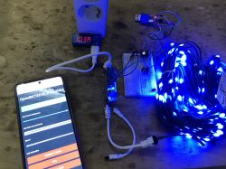
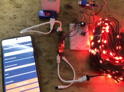


Summary .
The reader was right, the Tuya app crashes and you can't enter "dynamic" animations, but the firmware change was successful and now you can animate LEDs locally, without the cloud. The bar can also be freely configured and scripted, and you can even add a DHT11 sensor to it, for example, but about that another time.
The remote control also managed to work, I don't think I even need to mention the buttons?
Of course, the final configuration is up to the user, but I think I have explained the basics of commissioning sufficiently here.
There's microphone operation via ADC left to do, but I don't see much demand for that, so that's waiting in the queue for now.
Simple integration with Home Assistant is also available, as well as DDP protocol support, so you can control animations with WLED or XLights, I also presented this the other day .
And what functionality would you guys expect from a WS2812 Christmas tree controller? Feel free to discuss .
Cool? Ranking DIY Helpful post? Buy me a coffee.


