logo elektroda
logo elektroda
X
logo elektroda

Request for Help – Flashing Della Minisplit WiFi Module (WBR3 on TCWBRCU1)

dressyspider 3360 205
ADVERTISEMENT
  • #1 21536655
    dressyspider
    Level 2  
    Edit:
    I’ve started a detailed teardown and modification guide for the Della Mini Split TCWBRCU1 module. It’s a work in progress but may be helpful:
    https://www.elektroda.com/rtvforum/topic4125928.html

    Hey everyone,

    I’ve been digging into the WiFi module in my minisplit and could use some guidance on next steps. My goal is to run OpenBeken or another fully local solution — something cloud-free like LocalTuya, but flashed directly onto the device for better performance and independence.While I’ve tried LocalTuya in the past, I’ve run into permission issues, and I’d like to move away from Tuya entirely if possible.

    I will be updating this post with images later today. These will include pictures of the module, the internal layout, and the desoldered WBR3 module.If anyone has experience flashing WBR3 modules or working with minisplits like this, I’d really appreciate your input.

    Minisplit Details
    - Make:
    Della
    - Model:
    Optima Series
    - OEM Manufacturer:
    Align, Inc
    - Indoor Unit Model:
    048-TP-9K2V-23S-IN
    - Outdoor Unit Model: 048-TP-9K2V-23S-OUT
    - Amazon Link: Link
    - Type: Mini Split Air Conditioner
    - Cooling Capacity:
    9,000 BTU
    - Heating Capacity: 9,000 BTU
    - Power Supply:
    115V, 60Hz
    - Installation Type: Wall-mounted (Indoor), Outdoor unit with condenser coil
    - Features:
    WiFi control, Bluetooth capabilities

    The indoor unit has a removable USB WiFi + Bluetooth module. You can remove it by taking off the plastic clip that holds it in the housing, then sliding the module out.

    Module Breakdown
    - Main Module: TCWBRCU1
    - Soldered Chipset Module: WBR3

    The WBR3 is a separate module soldered onto the TCWBRCU1 board. I’ve opened the housing and taken clear photos of both modules and the internal layout. I haven’t desoldered the WBR3 yet, but I plan to do that later today to access the pins and take more detailed pictures for flashing.

    Chipset ID (speculation):

    Based on my research and comparisons to similar modules, I believe the WBR3 uses the Realtek RTL8710BN, which is part of the AmebaZ2 family. However, I haven’t confirmed this yet — some sources also mention RTL8720CF in relation to these modules. Once I can inspect the chip directly, I’ll confirm the markings.

    What I Know So Far

    - The WBR3 is listed as supported on the OpenBeken GitHub under the AmebaZ2 family (e.g., BW15, W701, WBR2, WBR3).
    - It may be flashable via UART, and I’ve found a walkthrough for flashing, so the process seems achievable.
    - The TCWBRCU1 base module is associated with the RTL8720CF, but the soldered WBR3 is likely doing the WiFi/Bluetooth work here.
    - However, I haven’t found a matching template for this minisplit model or module combination in OpenBeken, which is causing concern for the functionality after flashing.

    My Main Concern
    While flashing the module via UART seems feasible, my biggest worry is maintaining the full functionality of the minisplit post-flash. Without a template specifically for my minisplit model (048-TP-9K2V-23S-IN), I’m not sure if critical features (like temperature settings, mode switching, or IR control) will continue to work correctly once the firmware is updated.

    I want to ensure that I don’t lose important functionality after flashing OpenBeken or another local solution to the module.

    What I'm Hoping For
    - Be able to flash OpenBeken to the board
    - Configure the minisplit functionality (temperature settings, mode switching, IR control, etc.)
    - Create a device template once everything is working correctly
    - Provide the template to the community to help others with similar devices

    Reference Material
    - TCWBRCU1 Datasheet
    - WBR3 Datasheet

    AI: Once you have the WBR3 module desoldered, could you provide detailed photos or a diagram of the pinout and any markings on the chip? This will help confirm the exact wiring needed for UART flashing and chipset identification.

    Yes

    AI: Do you have any information (from the datasheets, PCB traces, or logic analysis) about the communication protocol between the WBR3 module and the main TCWBRCU1 board? Knowing whether it uses UART, SPI, I2C, or something else is key to ensuring OpenBeken can support all the minisplit’s functions after flashing.

    At this point, I haven’t fully traced or confirmed the communication protocol between the WBR3 and the TCWBRCU1 board. However, here’s what I’ve observed and what I plan to do:

    Pin Inspection (Planned): Once I desolder the WBR3 module later today, I’ll be inspecting and tracing the pins to determine how it connects to the TCWBRCU1. I'll also look at any silkscreen or labeled test pads for hints.

    Datasheets: The Tuya WBR3 datasheet mentions UART and PWM support, and some SPI/I2C capabilities, but it doesn’t explicitly describe how the WBR3 communicates in this specific configuration.

    Assumption (Working Theory): Since many Tuya modules communicate with their host boards via UART (e.g., simple serial commands for control and status), I'm speculating that UART is likely being used here. That said, I haven't validated this yet.

    Logic Analysis: I plan to probe the board and possibly do some logic analysis once it’s powered back up, ideally with the stock firmware still intact, to sniff communication between the WBR3 and the TCWBRCU1 if needed.

    TCWBRCU1_V1.0.0 & WBR3 Images
    Top view of the left WBR3 pins while still soldered to TCWBRCU1.
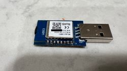
    Tuya WBR3 WiFi module on PCB with USB connector, top view, on a light surface.

    Top view of the right WNR3 pins while still soldered to the TCWBRCU1.
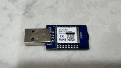
    Tuya WBR3 WiFi module with USB connector, top view showing label with model and serial number.

    Bottom view of the TCWBRCU1 while WBR3 is still soldered.
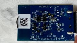
    Blue PCB with electronic components and a white QR code sticker.

    Closer image of the bottom view. I am fairly certain these are pass through holes to the WBR3 flashing pins. According to the datasheet, these should be pins A_0, A_1 and A_15.
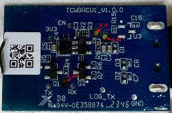
    Blue printed circuit board with electronic components, labels, and a QR code.


    Edit 1:
    Updated title and added images (Apologies for the cat hair in the pics).

    Edit 2:
    Updated additional mini split details.
    Added links.
    Helpful post? Buy me a coffee.
  • ADVERTISEMENT
  • #2 21536689
    p.kaczmarek2
    Moderator Smart Home
    Your device is most likely using TuyaMCU, so you can do the initial reading here:
    TuyaMCU flashing, setup and configuration guide - configure dpIDs for Home Assistant
    You can extract datapoints this way:
    Extracting DpIDs for TUYA MCU devices
    Once flashed, you can also use new Berry integration for data points that are not yet supported by OBK code:
    Berry scripting for various IoT platforms - tutorial for OBK new script integration part 1
    Don't worry if it seems much, we can do it step by step. So, for a start, I suggest two things:
    1. make detailed photos of device and what Tuya app offers, how is WiFi module connected, is it connected to the TuyaMCU via first UART port? Or is it a non-TuyaMCU solution?
    2. try to do it: Extracting DpIDs for TUYA MCU devices
    Helpful post? Buy me a coffee.
  • #3 21536711
    dressyspider
    Level 2  
    Thank you for the response!

    I've updated the initial post to include images of both modules. I believe there are passthrough holes available for programming the WBR3 without needing to desolder it from the TCWBRCU1 board. One of the pictures highlights which WBR3 pins are available through those holes, so it should make things a lot easier.

    I will attempt flashing the module tonight and report back my findings. I will also gather the requested images and update the initial post with them.

    The following datapoints were collected during my initial testing:

    Collected Datapoints via Tuya IoT Platform Website
    DPIDKeyNameTypeUnitRWRange/Notes
    1Power开关booltrue
    2temp_set设置温度valuetrue
    3temp_current当前温度valuefalse
    4mode工作模式enumtruecold, hot, wet, wind, auto
    5windspeed风速enumtruestrong, high, mid_high, mid, mid_low, low, mute, auto
    18humidity_current当前湿度value%true
    19temp_unit_convert温标切换enumtruec, f
    20Fault故障告警bitmapfalse
    23temp_current_f当前温度 ℉valuefalse
    24temp_set_f温度设置 ℉valuetrue
    101pm25PM2.5valuefalse
    102fresh_air新风enumtrueauto, low, mid, strong, off
    103freshair_filter新风脏堵boolfalse
    104SN_SW_verSN及软件版本rawfalse
    105sleep睡眠enumtrueoff, normal, old, child
    110markbit标识位bitmapfalse
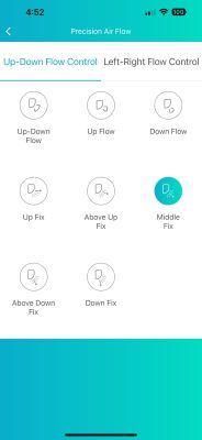
    113up_down_sweep上下扫风enumtrue0, 1, 2, 3
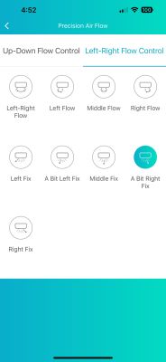
    114left_right_sweep左右扫风enumtrue0, 1, 2, 3, 4, 5, 6, 7
    115totalN电量整数valuefalse
    116totalP电量小数valuefalse
    119money省钱看的见enumtrue0, 1, 2, 3
    120energy发电机模式enumtrueoff, L1, L2, L3
    122fault2故障报警2bitmapfalse
    123boolCode布尔型stringtrue
    125airquality空气质量enumfalsegreat, good, middle, bad, verybad, veryverybad


    Smart Life Application Screenshots
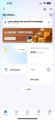
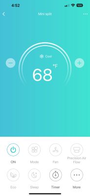
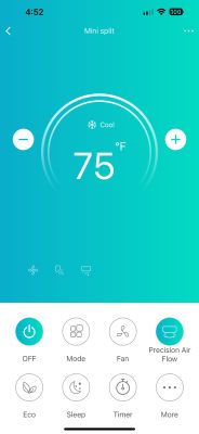
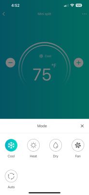
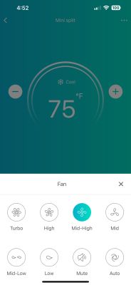
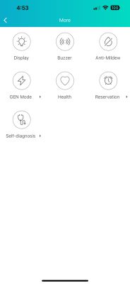
    Main screen of a smart home management app with device control options visible. Air conditioner control app screen showing 68°F cooling mode. Screen of an air conditioner control app, set to 75°F and cooling mode selected. Air conditioner control app screen set to cooling mode, temperature 75°F. Air conditioner control app screen set to 75°F in cooling mode, with fan mode Mid-High selected. Screen of an air conditioner app for controlling up-down air flow direction with various selectable modes. App screen for air conditioner's horizontal airflow control with multiple direction options. Mobile app screen with icons for functions: display, buzzer, anti-mildew, GEN mode, health, reservation, and self-diagnosis.

    Edit: Added Smart Life App screenshot images.
    Helpful post? Buy me a coffee.
  • #4 21536725
    p.kaczmarek2
    Moderator Smart Home
    This seems supportable, maybe not fully out of the box, but I can't see any serious problems. There are some data points that do not have a matching ChannelType in OBK yet but we can work on it. I can add channel types per request if needed, and we also have Berry scripting right now, so we should be able to figure things out.

    When flashing, make sure to get device backup first, so you can recover it if something goes wrong.

    I will also need to check whether UART and TuyaMCU drivers are already enabled on this Realtek platform, unless @divadiow and/or @insmod already know the answer? If they are not, we will need to enable them first.
    Helpful post? Buy me a coffee.
  • #5 21536915
    insmod
    Level 24  
    All realteks support UART, and TuyaMCU driver is enabled by default on all of them.
    Berry support will be added soon, also by default.
  • ADVERTISEMENT
  • #6 21536931
    p.kaczmarek2
    Moderator Smart Home
    This is better than expected. And my Berry integration is already able to parse TuyaMCU datapoints, as can be seen here:
    https://github.com/openshwprojects/OpenBK7231T_App/blob/main/src/selftest/selftest_berry.c
    I just need to prepare a tutorial for that.
    Helpful post? Buy me a coffee.
  • #8 21537252
    dressyspider
    Level 2  
    Thank you all for the information.

    I didn’t get home until later than expected yesterday, so I did not attempt to back up or flash. I will be trying in a few hours though and will report back.

    Added after 3 [hours] 15 [minutes]:

    >>21536969 Should I use this as a starting point or no?

    Added after 3 [hours] 12 [minutes]:

    My project is on hold for now. I tried using a solder sucker to desolder the WBR3, but it did not go very well. I was able to solder some Dupont wires to the WBR3 through the holes in the TCWBRCU1, and everything was looking good. That changed when I started wiring everything up on a breadboard. The trace for A_0 lifted, which is only the second time I have ever lifted a trace.

    It looks like I am now in the market for a new WBR3, and possibly a replacement TCWBRCU1 if I can find one. Unless I can desolder the WBR3, the scratch to expose some of the trace.

    I will post an update once I have a new module.
    Helpful post? Buy me a coffee.
  • #9 21537743
    divadiow
    Level 34  
    I guess there's no guarantee the dpIDs for the WBR1 version are the same, so probably not. If it was me I'd start by capturing boot log and de-soldering so a flash backup could be taken.
  • ADVERTISEMENT
  • #10 21540508
    p.kaczmarek2
    Moderator Smart Home
    You don't need realtek. You can use any module that fits and run obk. WB3S or CB3S also should be good, I believe. Or a WB3S-NiceMCU from Aliexpress (the one on BK7238, not BK7231T), altough I don't remember testing UART on the "Nice" one.
    Helpful post? Buy me a coffee.
  • #11 21540548
    dressyspider
    Level 2  
    >>21540508 >>21540508 Darn, I already ordered a replacement. It should be delivered soon. I also got some better tools for de-soldering SMB components. I'll be trying again tomorrow.

    Going to de-solder, then I will be exposing the trace and soldering to it directly to see if a dump/flash is still possible.
    Helpful post? Buy me a coffee.
  • ADVERTISEMENT
  • #12 21540765
    p.kaczmarek2
    Moderator Smart Home
    Well, the good side of having the same module as replacement is the fact that this will allow you to try or return to factory firmware as well.
    Helpful post? Buy me a coffee.
  • #13 21541593
    dressyspider
    Level 2  
    I was able to:
    - De-solder the WBR3 module from the TCWBRCU1 module, but lifting GND pad in the process
    - Repair lifted GND pad
    - Scratch the bus line for A_0 and solder a line to it
    - Solder all points to communicate with UART cable
    - Connect soldered points and UART adapter leads to a breadboard via dupont cables

    As I was unplugging the EN cable on the breadboard, the A_16 pad lifted from the WBR3. This time I could not repair the lift. These module boards are very fragile and/or I am very out of practice.

    I am curious about using a WB3S because I cannot seem to locate a reliable place to order the WBR3 from. The layout is a bit different though. Would this one work? There is a drop down to choose just the chip.

    Edit 1:

    Found and ordered the WBR3 on aliexpress

    Edit 2:
    Update: I will be able to try again and will be receiving a replacement on Friday (MST)(UTC-07:00). 
    Instead of de-soldering, I am printing this PCB workstation to make life easier. 

    I will update again after my next dump/flash attempt.
    Helpful post? Buy me a coffee.
  • #14 21544721
    dressyspider
    Level 2  
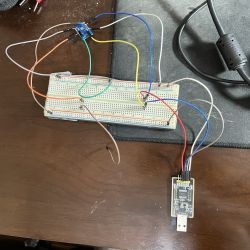
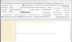
    @p.kaczmarek2 I was able to desolder the new WBR3. I have it connected to a UART adapter, but am not able to get past the "getting bus" message in BK7231 flash tool. Can you take a look at my wiring and let me know if you see anything obviously wrong?

    -This is what I have done after wiring everything up:
    -Verified it's COM4.
    -Tried the other preset baud rates.
    -Shorted EN to GND after clicking "Do firmware backup 'read' only". (I have also tried removing power from VCC on the WBR3 with the same timing)


    Breadboard with connected wires, electronic module, and USB programmer.


    Screenshot of the BK7231 Easy UART Flasher program showing connection bus failure errors.
    Helpful post? Buy me a coffee.
  • #15 21544726
    divadiow
    Level 34  
    Easy Flasher does not backup from or write to any Realtek chips. AmebaZ2 backups should be taken with ltchiptool for now and writing can be performed with AmebaZ2 PG Tool

    see https://www.elektroda.com/rtvforum/topic4097185.html for flashing. Tool downloadable from https://github.com/openshwprojects/FlashTools/blob/main/Realtek/AmebaZII_PGTool_v1.2.47.exe

    Please also backup and share the new module flash, it may contain interesting testing firmware.
  • #16 21544728
    dressyspider
    Level 2  
    >>21544726 Sweet, Thank you. I will try now. Also, I was planning on sharing the dump and creating a separate teardown for anyone else with the same/similar mini split models. :)

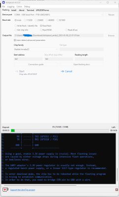
    Edit: Looks like it's backing up.

    Screenshot of ltchiptool v4.12.0 reading flash memory from a Realtek AmebaZ2 chip via serial port. 

    Added after 56 [minutes]:

    @p.kaczmarek2 @divadiow

    Do these files look correct? One is from choosing the "Read Flash" option and the other if from choosing "Read ROM". 
    Helpful post? Buy me a coffee.
  • #17 21544743
    divadiow
    Level 34  
    yes, the rom should be 384kb
    A list of IoT device ROM BIN files, each with a size of 384 KB.

    and your 2mb backup does boot

    Code: Text
    Log in, to see the code
  • #19 21547316
    dressyspider
    Level 2  
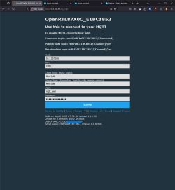
    I have successfully flashed the WBR3 and configured it to be on my IoT SSID.

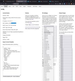
    Configuration page for OpenRTL87X0C_E1BC1852 device for MQTT settings, with fields for host, port, and user credentials.

    I am a bit confused here because the names do not line up with the data points that were collected earlier.
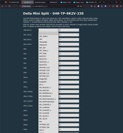
    Screenshot showing the configuration page of a Della Mini Split device in a browser, with pin settings and device details visible.

    Screenshot of the Della Mini Split configuration page showing a list of GPIO pin assignments and dropdown function selectors.
    Helpful post? Buy me a coffee.
  • #20 21547560
    divadiow
    Level 34  
    ah, it's TuyaMCU so no GPIO assignments. You'll need to start with something like https://www.elektroda.com/rtvforum/topic4038151.html

    There are many TuyaMCU devices in the device list that will probably show the journeys others have taken https://openbekeniot.github.io/webapp/devicesList.html

    example autoexecs for devices with TuyaMCU https://github.com/openshwprojects/OpenBK7231T_App/blob/main/docs/autoexecExamples.md

    looks like you've got your work cut out for you https://www.elektroda.com/rtvforum/topic4119999.html#21536711
  • #21 21547571
    dressyspider
    Level 2  
    I am genuinely curious, how can you tell? Im very new to flashing these kinds of chips and have only flashed Sonoff S31s with tasmota.

    Is it possible I flashed the incorrect BIN? I used "OpenRTL87X0C_1.18.99.bin"

    Also, would it make a difference if I swapped the WBR3 with another similar module? My guess is no because it appears the TuyaMCU handles the actual commands?
    Helpful post? Buy me a coffee.
  • #22 21548620
    dressyspider
    Level 2  
    Thanks for the links @divadiow . I went through them and they really helped clear things up. I have a better understanding of how TuyaMCU devices work now and I’m going to try the recommended approaches.

    I appreciate your help with this.

    Also, I managed to get my original WBR3 working again, so I guess I’ve earned myself another chance to break it! Haha. I’m thinking I’ll just keep that one stock for now as a backup.
    Helpful post? Buy me a coffee.
  • #23 21548807
    p.kaczmarek2
    Moderator Smart Home
    dressyspider wrote:

    Also, would it make a difference if I swapped the WBR3 with another similar module? My guess is no because it appears the TuyaMCU handles the actual commands?

    Obk runs on many platforms but, as far as i know, all popular WBR3-format modules have UART in the same place, just like TYWE3S, so as long as you get OBK-compatible module with TuyaMCU support it should work just fine. For example, CB3S or WB3S would certainly work.

    Altough... you may need first to double-check if the basic pinout is really matching. Ground, 3.3V, RESET, UART. Other gpio positions change between modules but it should not be a problem here...
    Helpful post? Buy me a coffee.
  • #24 21549144
    dressyspider
    Level 2  
    Thanks for the clarification. I am going to stick with the stock WBR3 for now since it appears to be functional and I am still able to communicate with it via OpenBeken.

    In the meantime I have ordered a link analyzer to capture and analyze UART traffic between the WBR3 and the TuyaMCU. While I wait for it to arrive I am gathering as much data as possible from the Tuya IoT platform using the original firmware. I am especially focusing on identifying which DPID values correspond to which commands like power control and timers and how they are structured such as types and timing fields.

    Once the analyzer is here I plan to correlate the cloud commands with the actual UART traffic to fully map out the control scheme. If I learn anything useful I will share it here in case others are doing similar TuyaMCU reverse engineering.

    Added after 6 [hours] 16 [minutes]:

    Quick recap of where I’m at:
    • I flashed OpenBeken 1.18.99 onto a WBR3 (RTL87X0C)
    • Reinstalled it into the TCWBRCU1 module, which is connected to a Della 048-TP-9K2V-23S-IN unit
    • MQTT is working with Home Assistant
    • The TuyaMCU driver loads fine, but I don’t have access to TuyaMCU_RX/TX roles in /cfg_pins
    • Commands like setTuyaMCUBaudRate and tuyaMcu_sendQueryState either aren’t available or don’t return anything useful
    • There’s no DPID logging even when I use the original IR remote
    • I know the Tuya Cloud API uses { "switch": "true" } to turn on the unit, but I haven’t found a working DPID or OBK command that does the same

    Am I using the wrong commands to test TuyaMCU comms with the RTL87X0C? I've tried the commands available in the cmd_tool section at "http://10.1.107.12/cmd_tool" and also within the webapp logs at "http://10.1.107.12/app?".
    Helpful post? Buy me a coffee.
  • #26 21549469
    dressyspider
    Level 2  
    Thanks, that actually clears up a lot. I had a feeling something wasn’t adding up with TuyaMCU.

    I’ll take a look at those links you shared, especially the TCL AC protocol ones. It makes sense now if this Della unit is using a custom serial format and not the standard Tuya DPIDs. That would explain why commands like tuyaMcu_sendState and setTuyaMCUBaudRate weren’t doing anything, and why I’m not seeing any DPID logs even when using the IR remote.

    I’ve got a logic analyzer arriving soon, so once I get some UART captures between the WBR3 and the main board, I’ll try to match it with what the Tuya cloud is sending. If it looks like the TCL format, I might go the ESPHome route or see if I can make a driver for OpenBeken.

    I’ll post whatever I find in case it helps others with similar setups.

    Appreciate the help!
    Helpful post? Buy me a coffee.
  • #27 21549472
    p.kaczmarek2
    Moderator Smart Home
    Interesting, I haven't seen such non-TuyaMCU device yet. I can try to draft a driver for it tomorrow if I manage to find some spare time.
    Helpful post? Buy me a coffee.
  • #29 21549694
    p.kaczmarek2
    Moderator Smart Home
    Which command would be most suitable for testing? Setting mode? Off, cool, dry?

    I'm porting one of linked drivers here:
    https://github.com/openshwprojects/OpenBK7231T_App/pull/1635

    Added after 2 [hours] 17 [minutes]:

    I've did quick port of single send.
    https://github.com/openshwprojects/OpenBK7231T_App/pull/1635
    Maybe @insmod can review.
    Usage:
    
    startDriver TCL
    ACMode 0
    

    then ACMode 1, ACMode 2, etc
    
    typedef enum {
    	CLIMATE_MODE_OFF,
    	CLIMATE_MODE_COOL,
    	CLIMATE_MODE_DRY,
    	CLIMATE_MODE_FAN_ONLY,
    	CLIMATE_MODE_HEAT,
    	CLIMATE_MODE_HEAT_COOL,
    	CLIMATE_MODE_AUTO,
    } climateMode_e;
    

    Reply parse is not ported yet, it seems one of the sends is using parsed reply, i hope it will not cause issues
    Helpful post? Buy me a coffee.
  • #30 21550109
    dressyspider
    Level 2  
    I tried running startDriver TCL, but it looks like the driver is not included in this build yet.

    OBK Log output:
    
    Debug:API:POST to api/cmnd
    Debug:CMD:cmd [startDriver TCL]
    Info:MAIN:Driver TCL is not known in this build.
    Info:MAIN:Available drivers: 
    Info:MAIN:TuyaMCU
    Info:MAIN:, tmSensor
    Info:MAIN:, NTP
    Info:MAIN:, I2C
    Info:MAIN:, BL0942
    Info:MAIN:, BL0937
    Info:MAIN:, CSE7766
    Info:MAIN:, DGR
    Info:MAIN:, Wemo
    Info:MAIN:, SM2135
    Info:MAIN:, BP5758D
    Info:MAIN:, BP1658CJ
    Info:MAIN:, SM2235
    Info:MAIN:, BMPI2C
    Info:MAIN:, CHT83XX
    Info:MAIN:, AHT2X
    Info:MAIN:, DS1820
    Info:CMD:[WebApp Cmd 'startDriver TCL' Result] OK


    The command still returns OK, but the driver does not seem to be active.

    What is the best way to try it out? Should I wait for a build that includes the TCL driver, or is there a recommended way to test it now?
    Helpful post? Buy me a coffee.

Topic summary

The discussion centers on flashing and integrating the WiFi module (WBR3 on TCWBRCU1 board) of a Della Optima Series minisplit air conditioner with a fully local, cloud-free firmware solution such as OpenBeken (OBK). Initial assumptions about the module using TuyaMCU were revised after UART traffic analysis revealed a custom protocol similar to TCL AC devices, requiring development of a dedicated driver. The user successfully desoldered the WBR3 module, backed up its firmware using appropriate Realtek tools (ltchiptool and AmebaZ2 PG Tool), and flashed OpenBeken firmware. Subsequent efforts focused on reverse engineering datapoints (DPIDs) from the Tuya IoT platform and correlating them with UART commands to control power, mode, fan speed, temperature, swing positions, buzzer, and display settings. A custom TCL driver was developed and iteratively improved with community testing, enabling control via OBK commands and Home Assistant (HA) integration through MQTT with discovery support. Challenges included mapping fan speed presets and swing modes to HA entities, handling temperature units (Celsius internally, Fahrenheit display), and managing UI elements and logs in OBK. The user contributed detailed testing logs, UI feedback, and feature requests, facilitating driver refinement. The project progressed to stable control of power, mode, temperature, fan speed, swing, buzzer mute, and display brightness, with ongoing work on UI polish and MQTT integration for seamless HA control.
Summary generated by the language model.
ADVERTISEMENT