 .
.
Here I will show how to change the software of a WiFi controlled LED light. The topic will cover its full disassembly, connecting the UART programmer, configuration and restoring the whole thing without glue. By the way, I will also reduce the LED current programmatically to extend its life a bit.
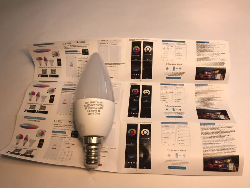
Let's start with the purchase itself. You can import such a lamp from China for as little as around £10. In our country, it is slightly more expensive. The whole thing can often be found under the name 'LED bulb', although this is just a colloquial name and is not correct. The unit shown here normally works with Tuya. Its designation is TY-E14-220VB*AT, WiFi LED Bulb RGB CW WW 5W AC. The RGB CW designation indicates the availability of colours and white temperatures. The second model name of the product is C3009.
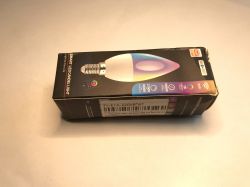
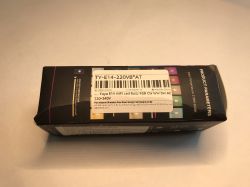
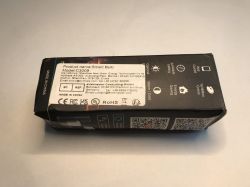 .
.
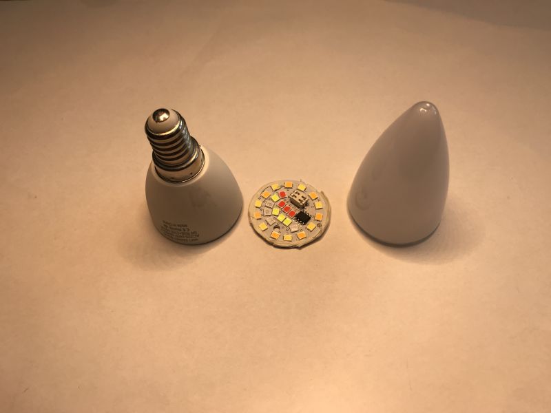
I first remove the dome, often just pulling harder, and then the LED board.
 .
.
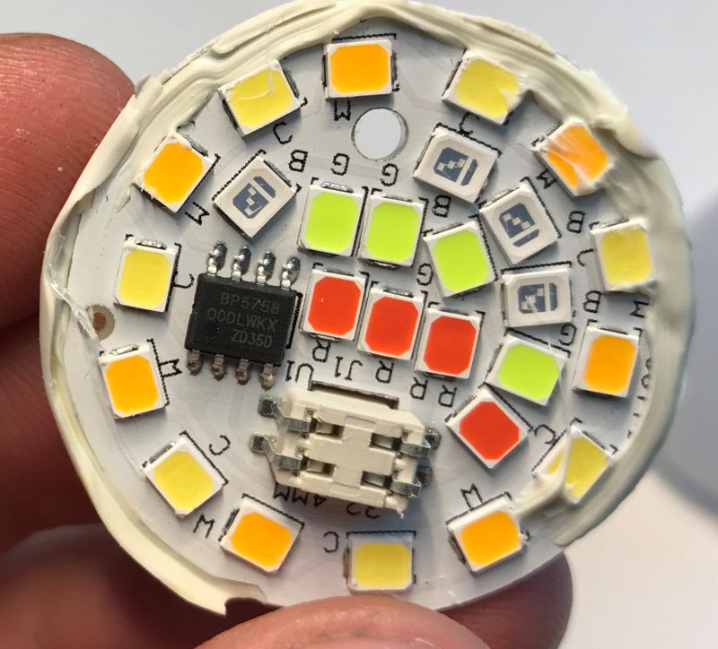
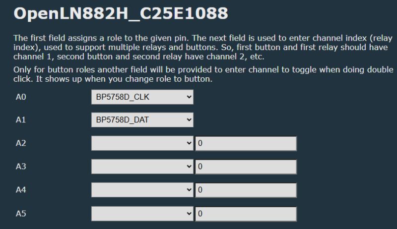
In this case there are five types - red, green, blue, warm and cold white. They are controlled by the BP5758.
 .
.
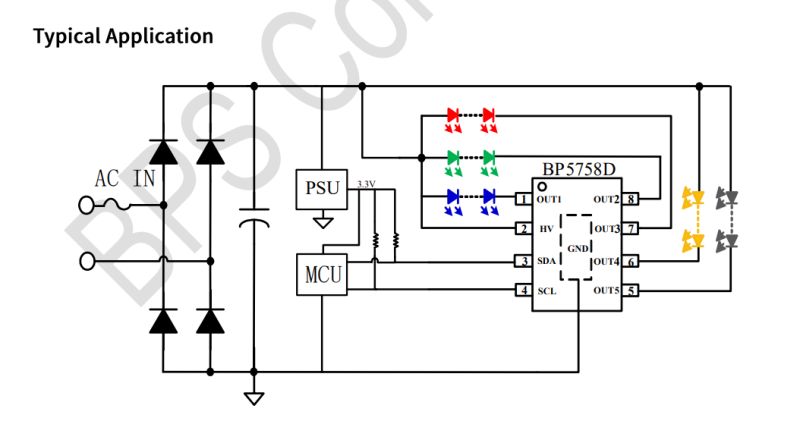
The BP5758 is a constant-current LED controller. It is distinguished by its control via an I2C-like protocol (without addressing), which reduces the number of lines needed from the MCU - just a data line and a clock, no five PWMs are needed.
 .
.
Our Polish firmware which I will upload already BP5758 supports.
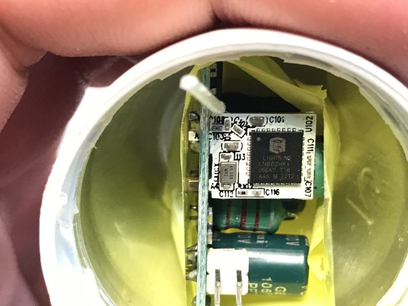
Below we have the board with the power supply and WiFi module:
 .
.
The WiFi module is based on the LN882H, which our firmware also supports:
LN882H datasheet, leads, WiFi modules (LN882HK, LN882HKx, LN882), firmware .
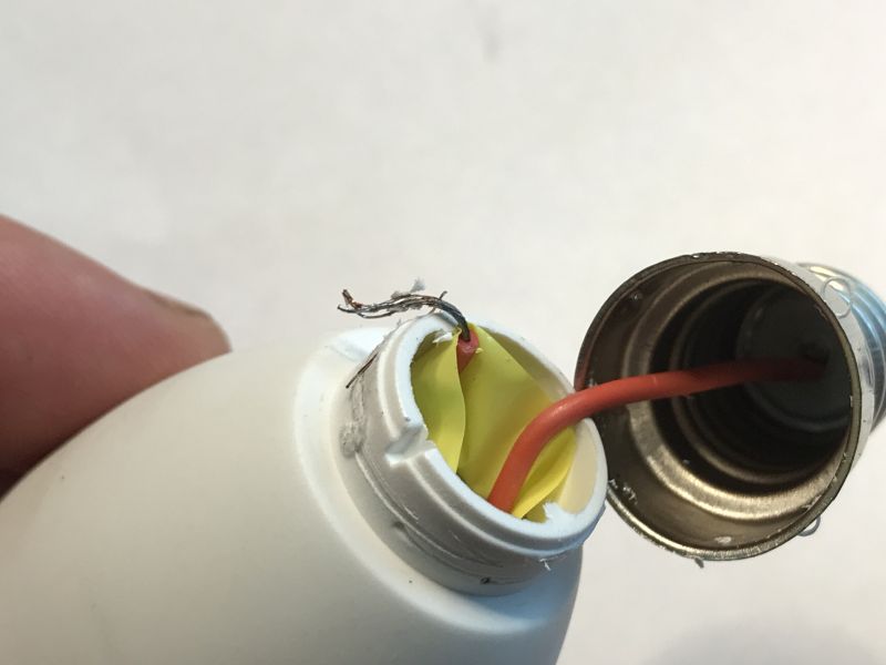
Now this board needs to be removed. First we remove the thread:
 .
.
Then we free the second wire:
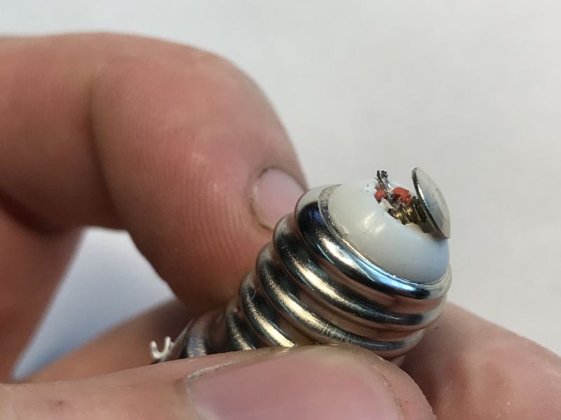 .
.
Done, now just don't lose the parts:
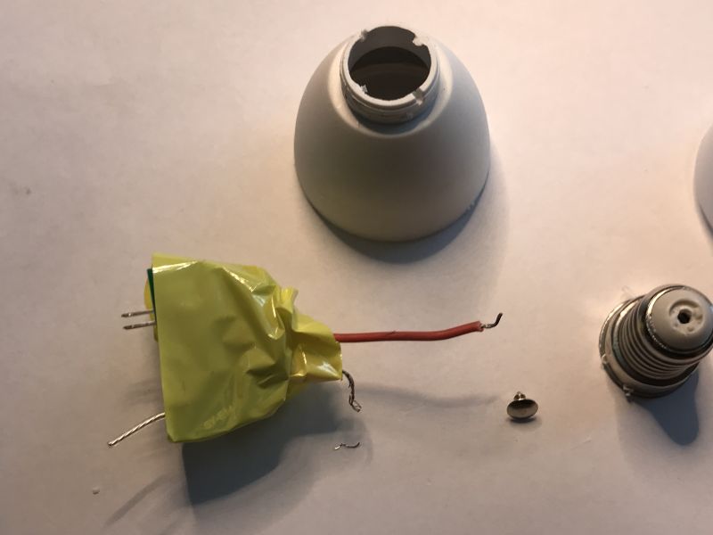 .
.
I don't recommend throwing away the tape either, unless you give it your own - it protects against shorting to the housing.
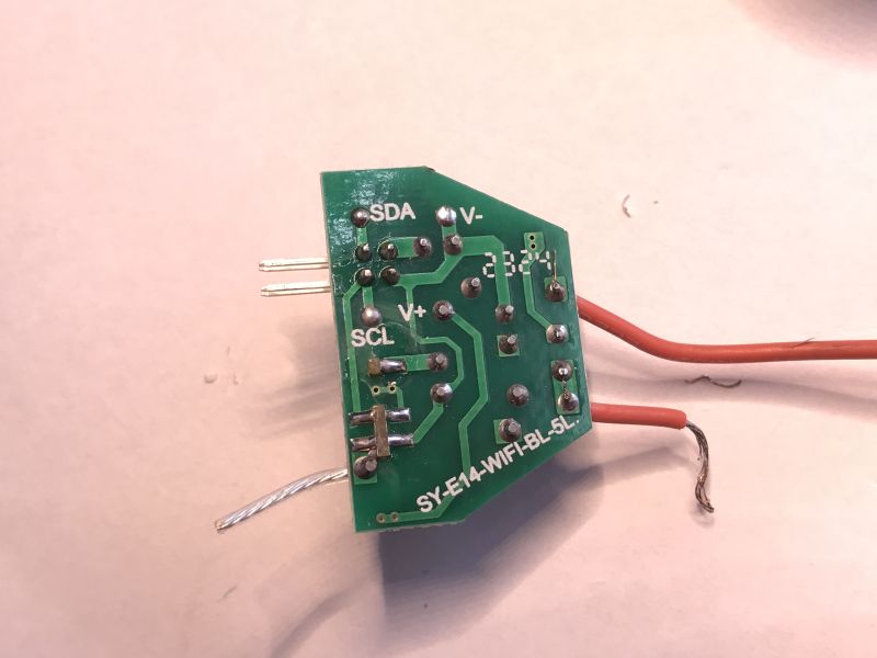
PCB designation: SY-E14-WIFI-BL-5L. The paths from the power supply and the two-wire bus are also marked.
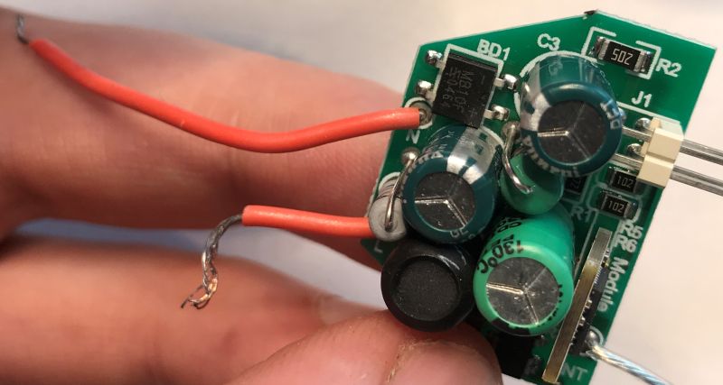 .
.
The rectifier bridge can be seen:
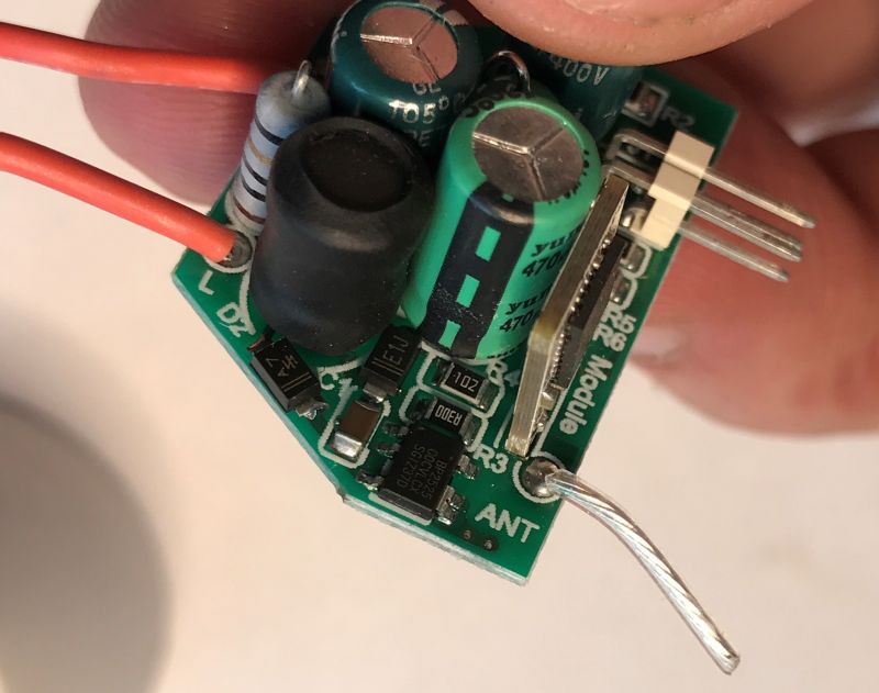 .
.
The antenna and power supply circuit - BP2525 - are visible next to it.
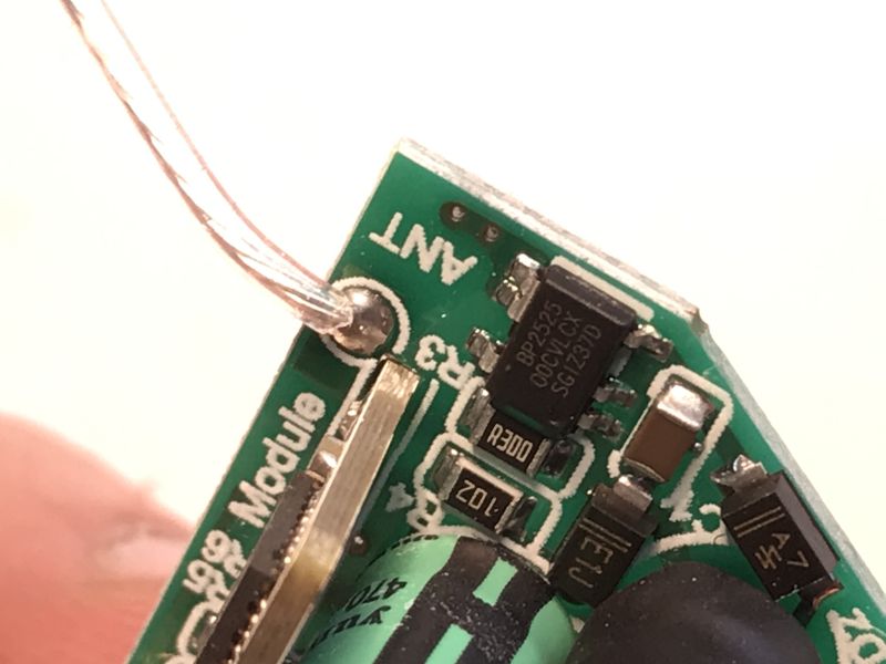 .
.
And here are the programming pads....
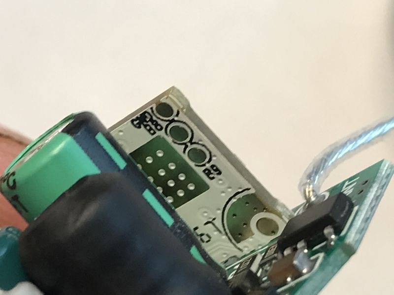 .
.
You have to solder out the WiFi module. Otherwise you can't get to the pads. My method for desoldering is flux and braid - once the binder is removed, the module falls out by itself.
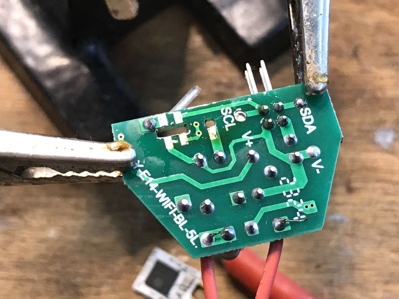 .
.
I then apply the binder to the pads - easier to solder:
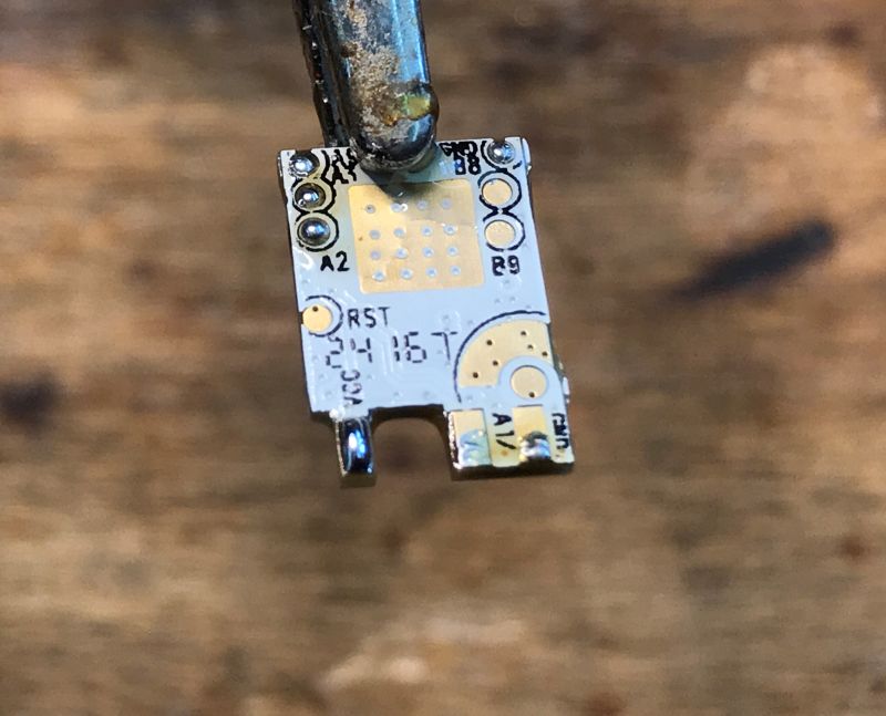 .
.
Marked leads:
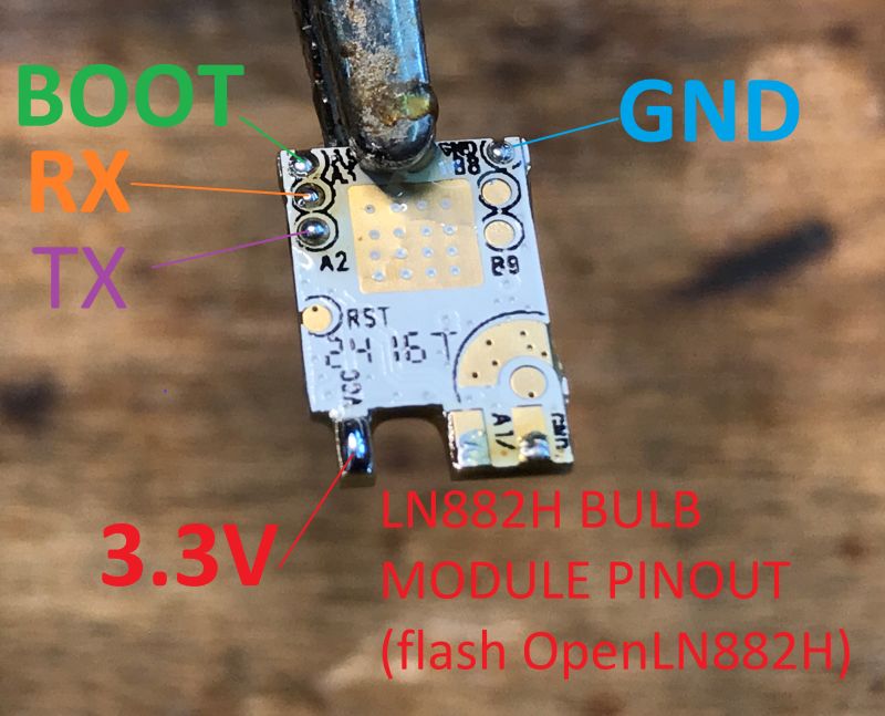 .
.
You will need a USB to UART converter for programming. Boot is connected to ground.
The cables are also taken before soldering.
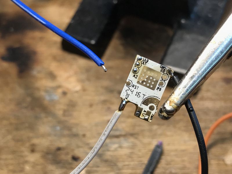 .
.
The whole circuit - an external LDO 3.3V is better than the power supply from the USB to UART converter, the WiFi module may not boot if the current capacity is missing.
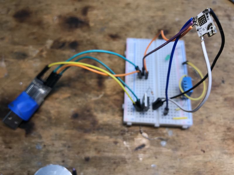 .
.
We used to flash the LN882H like this:
It is now supported by our flasher:
https://github.com/openshwprojects/BK7231GUIFlashTool
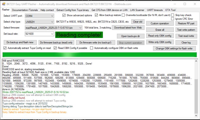
So, first batch backup:
 .
.
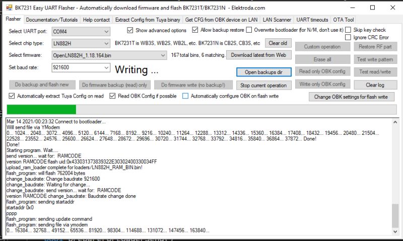
Then uploading the OBK - the flasher itself can download the binary file from Github:
 .
.
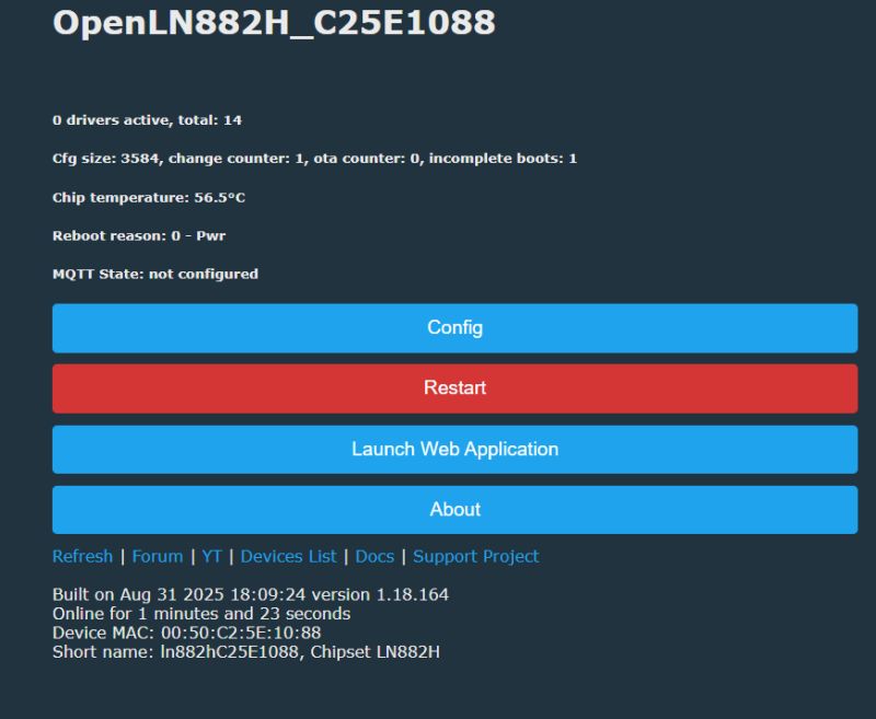
Then we disconnect the boot from ground and cut the power for a while. Then the AP should appear:
 .
.
You can configure our WiFi and device pins:
 .
.
You can set the pins manually:
 .
.
The easiest way is to upload the OBK template:
Code: JSON
Instructions for uploading the template:
Now it remains to explain the commands from the template. Normally they are edited in the "Short startup command" in the options:
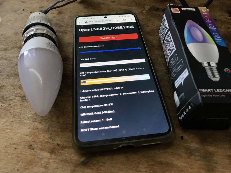
- BP5758D_Current 3 3 sets the current of the LEDs, separately RGB and separately CW. This reduces the heating of the whole and extends the life of the electronics
- LED_Map sets the colour order - this can be any colour order, and the firmware expects RGBCW
- PowerSave 1 activates power saving
 .
.
Selecting the current via BP5758D_Current allows us to decide between the lifetime and the level of brightness we want.
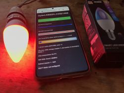
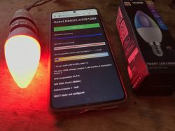
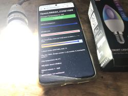
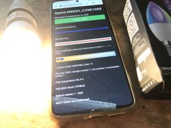
The final result (after putting it together):
 .
.
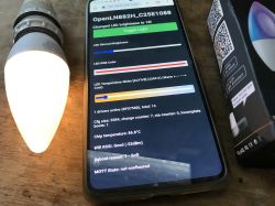
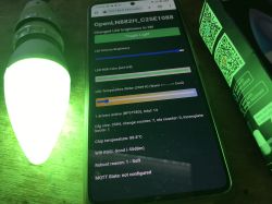
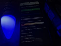 .
.
It remains to connect with HA, this is described in our tutorial: https://www.youtube.com/watch?v=pkcspey25V4
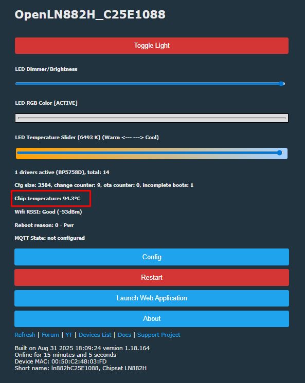
In summary, this is how to free the Tuya LED light from the cloud and pair it with the Home Assistant. This time, the biggest difficulty was to disassemble the whole thing, but it was able to be done without destroying it and after assembling the whole thing still works. There is also a potential problem with the product overheating, but this is already occurring from the factory and we can only improve it - by reducing the current of the LEDs through a suitable command. Without this we will quickly reach and 100°C:
 .
.
So much so, we now have control over this and can reduce the segment current if necessary. We decide for ourselves how much the LEDs will heat up. It's a much greater level of control than what the manufacturer's app offered us, so it was probably worth it....
In the next part I'll try to run animations on a few of these LEDs - I'll use the DDP protocol for this .
PS: Repository of the firmware used:
https://github.com/openshwprojects/OpenBK7231T_App
Cool? Ranking DIY Helpful post? Buy me a coffee.


