logo elektroda
logo elektroda
X
logo elektroda

uProg - small, fast, portable AVR programmer with SD

manekinen 154831 364
ADVERTISEMENT
Treść została przetłumaczona polish » english Zobacz oryginalną wersję tematu
  • #181 9826078
    Sebastian.R
    Level 20  
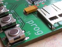
    I've already dealt with it, soldered a few insulated wires, quite thin so that the socket does not stick out too much. For those who do not know how to solder: Capacitor C5 - ************* (here I shot babola and sorry for him!), Diode D1 - Zenner - stripe towards the keys, please pay attention to the first pin of the chip - marked with a circle (if it is soldered incorrectly, it is a problem to desolder - better check 5 times or in the right direction), the LCD connector - solder with a clean tip with a small amount of tin and a little more rosin. It is best to solder the first pin, and then when everything fits, solder carefully from the other side.
  • ADVERTISEMENT
  • #182 9826205
    Gienek
    Level 37  
    Dla tych co nie wiedzą jak co lutować : Kondensator C5 -paskiem w stronę klawiszy S 
    Hasn't my colleague gone too far in his advice? C5 should be just the opposite (tantalums have a different marking than regular electrolytes). Photos from the first post mannequin show the proper soldering of this capacitor.
  • #183 9826229
    krzycho123
    Level 31  
    Exactly, in tantalum, the dash on the housing is PLUS and not a minus as in other elements. If you soldered the other way round, the system will not fire.
  • #184 9826236
    tmf
    VIP Meritorious for electroda.pl
    It will fire, it will fire, only literally. Tantalums give very effective firings :)
  • ADVERTISEMENT
  • #186 9827271
    krzycho123
    Level 31  
    tmf here you are right - unfortunately I do not have a photo, but recently, inadvertently to the charger on the max1811, I fastened the lapel inversely.

    Tantalum within 2-3 seconds desoldered from the PCB, fell off and burned a hole in the washer on which the system was located, I also do not recommend "firing" their soldered inversely ;)
  • #187 9827334
    manekinen
    Level 29  
    Sebastian.R wrote:
    I've already dealt with it, soldered a few insulated wires, quite thin so that the socket does not stick out too much.

    Maybe paste a few photos so that other people can easily cope with the installation of this type of socket? I am curious how it turned out and what it looks like :)
  • ADVERTISEMENT
  • #188 9836908
    Sebastian.R
    Level 20  
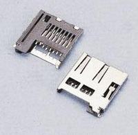
    I should buy such a socket:
    uProg - small, fast, portable AVR programmer with SD
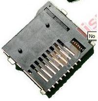
    But unfortunately I bought these:
    uProg - small, fast, portable AVR programmer with SD
    and I had to solder centimeter conductors - fortunately not all of them :) 8.
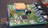
    It is worth noting that not all of them are needed. I recommend soldering to the socket first. The first pin of the socket and on the board is free. We solder the next 6. We don't need the rest.
    uProg - small, fast, portable AVR programmer with SD
    In addition, we bend the metal "legs" of the housing so that everything can be soldered to the PCB. Three without a problem, but this foot next to the capacitor burns the most because you have to bend it to match the GND mass.
    It's best to buy a suitable socket right away than to have a problem like me afterwards.
    The photo shows that everything is at a distance from each other and the February sockets do not close to the PCB. However, the soldered conductors have insulation on them, which has its diameter, so the socket sticks out a bit. Soldered, it reaches the height of the capacitor, so everything is OK. There will be no hassle with the display :) . It's best if the tile also had space for the second unfortunate socket.
    PS.
    Besides the difficulty of soldering, I report the need for this programmer to be also in the version programming ARM7 (JTAG) processors. Not that this ISP also has JTAG functionality, but second albeit a similar design for ARM programming.
  • #189 9843691
    jajen
    Level 17  
    I finally soldered the Microsd socket, copied the contents of the sd-files folder and I have sd-error. Could the 4Gb card be the problem? The device supports such cards. Unfortunately, I have no other to test.
  • #190 9843758
    krzycho123
    Level 31  
    jajen 4GB card will not work, if you read the whole topic from the beginning, you would know that SDHC cards (all over 2GB) do not work with this device.

    You must use a smaller card. [/ B]
  • #191 9843817
    jajen
    Level 17  
    I read, it says that the sdhc card is not working, but there is nothing that every 4gb card is sdhc. There is nothing written on mine except the company and capacity. But now I understand that all cards over 2 GB will not work.

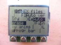
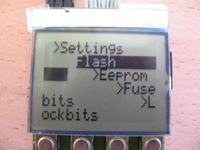
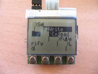
    OK, I got the card but there was another problem. What is the cause of shifted characters on the display? Pictures below.
    In addition, the startup logo is not displayed, but the menu appears immediately.

    uProg - small, fast, portable AVR programmer with SD uProg - small, fast, portable AVR programmer with SD uProg - small, fast, portable AVR programmer with SD

    OK, I am answering to myself. The reason was a bad LCD organization in the config.
  • #192 9853564
    krzysiekdg
    Level 13  
    You need to edit in notepad the file on the memory card simplify it in the system folder called config. when you open it with a notebook, it should look like this:


    : 00011111
    ||||||||
    ||||||| + ---- bit0 - programmer clock from osccal, programmer clock from osccal byte (1 = speed from OSCCAL byte, 0 = fabric 8MHz) (1 = speed from OSCCAL byte, 0 = factory speed)
    |||||| + ----- bit1 - AUTO VERIFY (1 = autoverify flash or eeprom after flashing)
    ||||| + ------ bit2 - AUTO ERASE (1 = erase the chip before programming flash memory)
    |||| + ------- bit3 - SHOW ANIMS (1 = play animations after failed programming)
    ||| + -------- bit4 - PROGRESS BAR (1 = enabled-slower programming, 0 = disabled-normal programming)
    || + --------- bit5 - HEX FILES (1 = hex, 0 = bin)
    | + ---------- bit6 - Slower SPI clock for LCD, slower clock for LCD (1 for 2MHz, 0 for 4MHz)
    + ----------- bit7 - LCD organization, LCD organization (1 = 48 * 102 (chinese), 0 = 48 * 84 (normal))

    : AF = lcd contrast, contrast (HEX)
    80 - converter off, converter turned off
    81 to FF - contrast voltage from min to max, inverter voltage from min to max


    : 14 = lcd bias, multiplexing (HEX)
    10 to 17 - see PCD8544 datasheet, see note

    : 8 = programming speed start, initial programming speed (DEC)
    8 - 8MHz (default, default)
    7 - 4MHz
    6 - 2MHz
    5 - 1MHz
    4 - 500kHz
    3 - 250kHz
    2 - 125kHz

    : FF = osccal value, osccal value (HEX)
    00 to FF - internal oscilator calibration from 4MHz to 16MHz, internal oscillator calibration from 4MHz to 16MHz

    Programmmer use values preceded by a colon. Rest of the text can be freely modified. Do not put any colon chars.
    The programmer uses values preceded by a colon. The rest of the text can be freely changed. Colons should not be used.


    Save your changes and you're done.
  • #193 9853694
    manekinen
    Level 29  
    This file has changed with the updates, a lot of things have changed in general, and you have to read the description and then the whole topic exactly to keep up with it. In the next update, I will correct the description so that it is up-to-date.

    Changing the display organization is of course bit7, by default, after downloading the files, there is one, which allows you to work with the replacement, i.e. as it is (were) available to me. You must enter zero for the original.

    I remind you to report correct (or not) operation with different tested systems, then I will add to the list :)
  • #194 10030257
    manekinen
    Level 29  
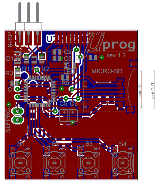
    Hello. In the attachment there is a design of the board in the 1.2 . Changes from 1.1:
    -added LED in housing 0805 or 1206 + resistor for it, this LED will flash during some operations, e.g. when switching on or counting the size of the HEX file. It is partially supported in the last firmware, in the next I will add some simple debugging, so that if something with the system is wrong, the LED will tell us about it :)
    -added pads on the bottom side of the board, for any elements in 0805, SO8, and SOT223 housings. Thanks to this, the programmer can be expanded with its own stabilization and charging system, or add your own converter, e.g. on dedicated systems - who needs what. A very nice solution was suggested by a colleague MatygaD , now such a layout can be made without an additional tile :)
    - VCC, ADC, and PWM (round) pads are also derived from the bottom side, if in the future there will be some functions using these pins, you will be able to modify the board without any problems :)
    -removed CR2032 battery pads because they were too weak to use the system practically - working time 10-15 minutes.

    From (I hope) Monday I am starting work on adding Xmega support - if someone has several models and can test the system, I invite you to PW. I mean a beta tester who would find some time to check the operation with subsequent versions of the program - for such a person I can send a 1.2 plate and a display as a gift :)


    uProg - small, fast, portable AVR programmer with SD
  • #195 10046497
    wojnar
    Level 17  
    manekinen wrote:
    ...
    -added pads on the bottom side of the board, for any elements in 0805, SO8, and SOT223 housings. Thanks to this, the programmer can be expanded with its own stabilization and charging system, or add your own converter, e.g. on dedicated systems - who needs what. A very nice solution was suggested by a colleague MatygaD , now such a layout can be made without an additional tile :)

    Hmm, it's a pity that instead of one SO8 there is no layout under the MCP73113, when the fields are to facilitate the construction of, for example, a charging bag based on this system :cry: .
  • ADVERTISEMENT
  • #197 10047973
    krzycho123
    Level 31  
    mannequin , I honestly do not recommend this method, especially the use of such silverware as in the video from EEVblog.

    In these cases it is very easy to break the pads by soldering such a stiff wire and then bending it.
  • #198 10063941
    marlech
    Level 11  
    Hello and welcome !!!

    I have a problem, namely the system powered by 3.3 V, while the display shows 1.1 V, the uProg seems to be working properly. What could be causing this.

    greetings
  • #199 10064030
    manekinen
    Level 29  
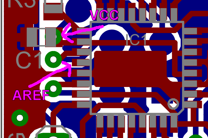
    Do you have a 1.2 tile? I disconnected the reference voltage of the AREF foot on it so that it can be selected programmatically, in all batches that have been there so far, the voltage is set from this foot. In the next program, it will be software-selected, and it will work with the 1.2 and earlier boards.

    Heh, I completely forgot about it :oops: It does not bother you in programming, well the fact that the system will not measure the voltage and it will turn on even if we give 5V - you have to remember about it.

    My intention was also to add temperature measurement and battery charging current measurement (programmed charging, which I gave up because it was not very safe) and this required an internal reference voltage of 1.1V.

    If you want to restore the measurement until the next update, connect the AREF pin to the system's power supply:

    uProg - small, fast, portable AVR programmer with SD
  • #200 10081030
    marcin44430
    Level 16  
    Hello.
    Can I use 75? or 1k? instead of 330? resistors, because I only have these.
  • #201 10081463
    piotrva
    VIP Meritorious for electroda.pl
    Hmm, these are current limiting resistors (protecting uProga) when programming 5V powered systems - 75R may be a bit too little (in extreme situations), and 1K is a bit too much - you may have problems with programming sometimes.
  • #202 10081882
    marcin44430
    Level 16  
    And 220? will be ok :?: or 510?.
  • #203 10083745
    piotrva
    VIP Meritorious for electroda.pl
    220R should be ok
  • #204 10113472
    marcin44430
    Level 16  
    Hello.
    Could someone post a screen on how to set up fusebits in bascom. :cry:
  • #205 10115225
    garlinski
    Level 13  
    Use the online fuse-bit calculator: www.engbedded.com/fusecalc (you have to choose ATMega 328P and enter fuse bits in hex form), or install eg Burn-O-Mat, there you can enter fuse-bits directly in hex form), and programming is much faster.

    PS: The programmer is great, it has already made my life easier several times.
    Regards.
  • #206 10116045
    marcin44430
    Level 16  
    Hello.
    I have avrdude and burn-o-mat overlay, but I get a bug that I don't think it supports Atmege328. Because it is not even on the list of supported microprocessors in avrdude.

    Added after 1 [hours] 47 [minutes]:

    I set the Fusebits as shown in the picture below, but the Uprog does not work, i.e. when turned on, only the horizontal dash on the display blinks and nothing. :cry:
    uProg - small, fast, portable AVR programmer with SD
  • #207 10116389
    manekinen
    Level 29  
    Marcin, it will work even if you don't set these leaves - only 16 times slower.

    marcin44430 wrote:
    when turning on, only the horizontal dash on the display will blink and nothing.

    Such a dash lights up when switching off, at least for me.

    Have you toyed with the contrast settings? If not, play, maybe the system works, but you can't see anything.
  • #209 10116828
    marcin44430
    Level 16  
    garlinski already coped with the programming of the system.

    Added after 8 [minutes]:

    manekinen wrote:
    Marcin, it will work even if you don't set these leaves - only 16 times slower.

    marcin44430 wrote:
    when turning on, only the horizontal dash on the display will blink and nothing.

    Such a dash lights up when switching off, at least for me.

    Have you toyed with the contrast settings? If not, play, maybe the system works but you can't see anything.


    I spelled it a bit wrongly, it is not a dash like when it is turned off, but it is dashed like a narrow piece of text (logo) and it appears either at the top or in the middle.

    Added after 9 [minutes]:

    I also have a question whether the entire sdfiles folder should be copied to the card or only its contents.
  • #210 10116944
    garlinski
    Level 13  
    The content of the SDFILES directory on the card, mine (Kingston 1GB) was not detected when formatted in FAT32, but started with FAT16. Without a card, it should also fire with information about the lack of a card and display the main menu. Perhaps the fault is the contact of the display with the pins of the socket on the board - see if the paths coincide with the contacts.

Topic summary

The discussion revolves around the uProg, a compact and portable AVR programmer that utilizes SD cards for firmware storage. Users express admiration for its design and functionality, highlighting its small size (44 x 39 x 5.5 mm) and fast programming speeds (write: 12.5kB/s, read: 14.5kB/s). Several users inquire about compatibility with various components, such as different LCD displays (notably the Nokia 3310's LPH7779), and the ability to program various AVR microcontrollers, including the ATmega328P and ATtiny series. Issues with SD card compatibility, particularly with SDHC cards, are frequently mentioned, as well as problems related to fusebit settings and display contrast. Suggestions for improvements include adding a battery charging system, enhancing the user interface, and providing better documentation for setup and troubleshooting. The community shares experiences with different configurations, troubleshooting tips, and modifications to enhance the programmer's capabilities.
Summary generated by the language model.
ADVERTISEMENT