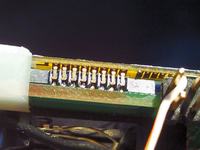
The contacts coincide. Maybe the display is damaged?

Czy wolisz polską wersję strony elektroda?
Nie, dziękuję Przekieruj mnie tam
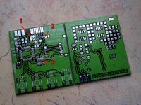
manekinen wrote:Buddy, is there a transition on the board from the Prock legs to the contacts? I am asking because someone had a case that the grommet on the PCB did not connect, and it was a shallow one from me. Unfortunately, there can be such a nasty passage that has a life of its own.
manekinen wrote:Tile in what version? You can add the led as it is in version 1.2, and during startup the led should flash 2 times quickly. At least it will be known that the system is correctly programmed.
mlassota wrote:Hello
According to me, you have a good display, but most likely your inverter powering the contrast does not work.
what voltage do you have on pin 7 of the display - the one that is connected only to the capacitor (relative to GND) From what you know, you need to change the setting in the Config file to the "original" display
What kind of contrast capacitors do you have? 100n? Maybe it's not enough ...
Regards
M.

manekinen wrote:
manekinen wrote:Oh, 5.27V on the display is a bit too little, I don't remember exactly, it should be around 7V. Does increasing the contrast in the file increase the tension? Because it should.
manekinen wrote:I hope that the capacitor C5 + C6 is at least 20uF? Although it may not be enough for a 2GB card.
manekinen wrote:If the voltage fluctuates, it means that the file from the card is being read and we can only blame the display. Maybe it is not LPH7779 but a similar one? Have you tried to change the display type in the config?
manekinen wrote:Try also in the dark to perform some operation on the prock, write or read flash, see if something is happening (i.e. creating a file on the card or at least resetting the target chip). If it's okay, then the real display remains.
manekinen wrote:You can also measure the voltage on pin 7 of the display when it is in the phone.
Quote:but i understood from fuse calculator www.engbedded.com/fusecalc/ that 07 means that divisions are turned on, and 87 - not turned on. So how little would this extended byte to software 07 or 87 be?Fusebity: Ext: 07, high0, low: A2
(internal 8MHz oscillator without / 8 split, CLKO output on, 2.7V brown-out detection, reset vector to bootloader address, 4kB bootloader memory, EESAVE on)
piotrva wrote:Yes, now I saw the confusion.
manekinen wrote:If you are programming avrdude, write Ext: 07, high0, low: A2
If another program, write Ext: FF, high0, low: A2
I don't know why, but avrdude misinterprets unused bits as "0".

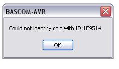
marcin44430 wrote:It looks like no program supports atmega328.
marcin44430 wrote:I have no idea what to do anymore. I bought a PCB from the author, everything was carefully assembled and programmed for the 3rd time and still the same. You can't see anything on the display, and you can perform various operations blindly.
