The driver for HF pickup is modified. No converter needed. Obviously the reception is not that good, but it is possible

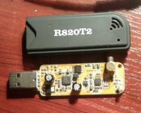
Let's say up to 40m is basically satisfactory. First, install the driver from Zadig and then upload the file from the attachment to SDRSharp. The system will ask if you want to replace the existing one, give OK and it's ready. In fact, even 80m is walking, but too weak for me. One more piece of advice. Please add gain accordingly in settings. The lower the frequency, the higher the gain must be. Direct Sampling can be forgotten. With this driver, it is a waste of time and the risk of damaging the tuner. I will add that it is good to do chip cooling. The shielding itself is not as important as cooling. I use soldering points under the circuits. I put a lot of tin into the holes and then solder, for example, a flat spiral made of thick copper wire to the drop. Before soldering such a spiral, you need to unwind about 2 cm of the wire and then, after soldering under the chip, a plate should be soldered to the tip. Or solder the tip to the housing - a tin can for the old head is perfect. The antenna output can be converted to BNC. I did it this way. I took the BNC socket and used the coaxial cable retrieved from the laptop lapel. It was a hatch with a broken die

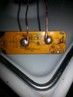
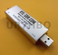
I soldered the cable to the socket. I will not describe the way of earning money, because it is not a topic. I soldered the other end to the tuner hot spot. That is, where the original socket introduces the signal. For example, for the middle pin of the MCX socket. I soldered the BNC socket to the casing on the head, the tuner board was soldered to the casing on spiral wires, which are soldered with the flat side under the chips. As for the diameter of the wire, don't overdo it, about 2mm is enough, maximum 3. Of course, the thicker the wire, the better it will dissipate heat to the housing, but ... the harder it is to solder. You cannot overdo the heating under the chip, so as not to desolder the system and damage the PCB. The holes under the chip have such tubes inside. If one is overheated, it will move away from the PCB. It is true that there is no hole, but it will not pull the tin. The purpose of the tin is - because normally these systems should be soldered from the bottom, and often they are not, the mounting of the system from the bottom, and in our case it is also a heat conductor and element fixing the wire helix. The spiral can be replaced with a thicker plate. I have a copy where instead of a helix I soldered 5gr and a wire ear with a diameter of 6mm to the coin. Such a "U", a few cm high, cools very well, but can be hot. The question is, if there was no cooling, how would the chip heat up? And it can reach a temperature of over 70 degrees. And here we go back to the driver. If the device operates in the range not provided for the tuner, there are still quite extreme conditions, and the effects of the system operation may be unsatisfactory. Cooling results in a significant reduction in noise, which increases the sensitivity. The picture shows a soldered spiral with some sections - "thermowell"



 260044308_...rev025.jpg Download(16.78 kB)
