logo elektroda
logo elektroda
X
logo elektroda

RTL-SDR - an SDR receiver from a cheap DVB-T tuner on a USB connector

Ganjor86 681364 1593
ADVERTISEMENT
Treść została przetłumaczona polish » english Zobacz oryginalną wersję tematu
  • #211 13583727
    BOOM i ZONK
    Level 21  
    This is how we perceive these stations ... It is the bane of these dongli. In my case, wrapping the plate with copper foil helped a bit, it cut the weakest ones and the really strong ones moved to the area of 35-45MHz where there is not much interesting. This was reflected in the higher frequencies where some mirror frequencies appeared. As for the Sample Rate, I noticed that the lowest settings improve immunity to very strong signals, as if the receiver was becoming deaf but maybe it's just an illusion because I haven't done any tests. And the maximum ones, in my opinion, are not practical because once you can't see anything on this waterfall, two before you tune in, the transmission will usually end. You need to know what you want to listen to. On the newer computer I use 2.4MSP's, it is enough to cover the whole 2 meter band with small chaks and the computer can be used normally.
    Well, you don't look in the teeth of a gift horse.
  • ADVERTISEMENT
  • #212 13583795
    OK2STO
    Level 20  
    Hello, I also made this UP converter s TA 7358 and the whirring is not sensitive, but it is whirring, I have s Xtalem 40 MHz.
    Jard
  • #213 13605205
    methyl
    Level 16  
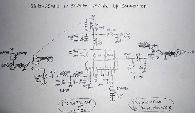
    Let someone who knows more about the topic of the low-pass filter for the converter from this scheme:

    RTL-SDR - an SDR receiver from a cheap DVB-T tuner on a USB connector

    At the input there is "Rf Gain" in the form of a potentiometer and after it begins a filter that cuts above 30mhz.

    There is one "but". This filter has the correct characteristics as long as it is deprived of this capacitor at the 10nf input.
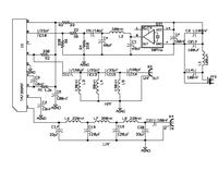
    The layout simulated in the program for designing such filters showed that it gets terrible.

    RTL-SDR - an SDR receiver from a cheap DVB-T tuner on a USB connector

    without this capacitor at the input it is ok:
    RTL-SDR - an SDR receiver from a cheap DVB-T tuner on a USB connector

    I am not a radio alpha and omega, so let someone expert in the subject say here, because it turns out that a lot of people build faulty systems with a silencer at the input instead of a filter.

    Nowhere in the diagrams of this type of filters have I seen a capacitor in this place.

    Check it out because I may be wrong due to lack of knowledge, but if not, it's time to dump that cond.
  • #214 13605210
    androot
    VIP Meritorious for electroda.pl
    How did you simulate it? You ensured the source and load impedance (probably 50? ;) ?
    This capacitor should be a short circuit for the RF frequency.
    Instead of a potentiometer, it is better to use a 50? regulated attenuator.
  • #215 13605223
    methyl
    Level 16  
    50R in and out impedance set.
    If I reduce the value of this capacitor, it starts to get nice.
    It is possible that I am performing the simulations incorrectly.

    I simulated this LPF in the same way:

    RTL-SDR - an SDR receiver from a cheap DVB-T tuner on a USB connector

    and without this 100nF at the input of the filter is beautiful and sharp and with this capacitor it shows me that I will not hear anything because the attenuation is in full range.

    Out of curiosity, I will probably fire up such a system under a tuned generator and see how it behaves.

    I find different versions of these filters on the net. Without this conda at the input and with:

    RTL-SDR - an SDR receiver from a cheap DVB-T tuner on a USB connector

    I guess I'm doing the simulations wrong. How do I swap this capacitor and the 50R resistor responsible for the impedance, it is ok.

    Time to talk to someone smart ;)
  • #216 13607707
    androot
    VIP Meritorious for electroda.pl
    Give a screenshot of the schematic you simulate.
  • #217 13607968
    sb8gapi
    Level 14  
    Hello
    I built two presented versions of converters (I have posted these diagrams themselves on the forum). I additionally have a BAV99 protective diode at the input (there can also be two 1n4148) and the aforementioned 100 nF capacitor and everything works without any problems.
  • ADVERTISEMENT
  • #218 13608524
    defenders
    Level 11  
    Hello,

    I have a question for my colleagues, is there a program for windows7 that allows you to scan several or a dozen frequencies previously set?
    I connected the tuner to the computer (server) and 2x5 / 8 antennas on 2m, I connect to the computer via teamviewer from my smartphone, which gives me the option to change the settings and the sound is buffered to the smartphone via soundwire ... This solution, however, has limitations to listen, I need to be logged in via WIFI :( I am looking for a program that will allow streaming via the Internet to a smartphone and then a bluetooth headset, while driving a car I will be able to listen to the band from a stationary antenna and a scanner would be very useful :D Thank you in advance for understanding my whim ;)
  • ADVERTISEMENT
  • #219 13617219
    mkpl
    Level 37  
    Has one of your colleagues watched what the signal from the 50MHz generator looks like after the filter and at the LA1185 input? In my case, a tragedy ... A lot was achieved by using a 16MHz generator and a frequency triple.
    I am currently testing this circuit and it is kind of less rubbish
  • #220 13617648
    lysy1980
    Level 33  
    I have a sine wave after the filter.
  • #221 13617686
    mkpl
    Level 37  
    What is the amplitude of the signal at the input of the chip? According to the catalog card, about 235mV RMS should be
  • #222 13617846
    lysy1980
    Level 33  
    If I remember correctly, something around 400mV. Tomorrow after work, I will take a look again, because I have 2 converters with generators from different manufacturers.
  • #223 13618580
    methyl
    Level 16  
    Question for those who did la1185 / la1186 / ta7358 converter with quartz instead of generator.

    Didn't you get quartz on the fundamental frequency?

    In this converter, the quartz should work at a frequency higher than the lowest received by the SDR, in my case f> 24MHz.

    What I wouldn't put under the scalak, it oscillates at 9-15MHz.
    So far, I have successfully assembled KF to SA612 (ne612) converters using a 50MHz generator. I wanted to compare the TA7358 chip with quartz but as you can see there are difficulties.

    Of course, you can add a system from several elements that will excite such a quartz on the 3rd overtone or put a generator there and everything will be great, but I saw that you were doing this set on quartz without such combinations.

    best regards
  • #224 13618627
    OK2STO
    Level 20  
    Hi, I was doing this converter with a 40 MHz generator ground from the old computer mainboard and I had no problem, then I bought a generator in a 5O MHz store and it is also fine. I thought I would make a quartz, I have 50 MHz, it would be a bit more difficult, I went to latwizne- generator.
    Best regards.
  • #225 13620191
    lysy1980
    Level 33  
    As promised, I checked and it is ~ 400mV RMS on TA7358 input, KOYO brand generator, 50MHz. I did not check the second one, a lot of undressing, I know that the SJK generator is sitting there.
  • #226 13631203
    mkpl
    Level 37  
    I put in a different generator and it's better. On the oscilloscope, the signal looks like a sine wave, but ... it strongly depends on the time base set (RIGOL 100MHz oscilloscope). The problem with the shape of the generator signal is mainly in the band of the oscilloscope. Because the 100MHz bandwidth will filter it to sine, unfortunately.

    I have a problem with the tuner itself. When it warms up, the RTL SDR freezes. It helps to connect temporarily and connect after a while. It seems to me that the tuner is overheating and breaks communication even though the system does not see the problem. Have any of your colleagues faced a similar problem?

    In terms of noise, it is brilliant to wrap the tuner with aluminum foil and connect it to the housing of the USB plug, in addition, I have a ferrite filter (5 turns) on the cable and power the tuner not from USB, but an external power supply from which I also power the converter.
    This allows you to get rid of these "teeth" in the band.
  • #227 13631868
    lysy1980
    Level 33  
    mkpl wrote:

    I put in a different generator and it's better. On the oscilloscope, the signal looks like a sine wave, but ... it strongly depends on the time base set (RIGOL 100MHz oscilloscope). The problem with the shape of the generator signal is mainly in the band of the oscilloscope. Because the 100MHz bandwidth will filter it to sine, unfortunately.

    I use Philips up to 50MHz and if I didn't set the time base, there is a sine even after zooming in on a segment of the waveform.


    mkpl wrote:
    I have a problem with the tuner itself. When it warms up, the RTL SDR freezes. It helps to connect temporarily and connect after a while. It seems to me that the tuner is overheating and breaks communication even though the system does not see the problem. Have any of your colleagues faced a similar problem?


    I had a similar problem with the tuner, the symptoms intensified and the tuner finally worked only when it bent around RTL2832U, Raising the RTL system and tuner and re-soldering with new tin and flux did not help.
  • #228 13632010
    methyl
    Level 16  
    Maybe I will not bring much to the topic, but I ran the TA7358 converter not with quartz because, as I wrote, it was excited at the wrong frequency, but with a 50Mhz generator and it's ok.

    I have been playing with SDR converters and with the SDR itself for a long time, I compare different mixer solutions and the effects they give upon receipt.
    I noticed that the SA612 (NE612) is better, however.
    With the same input filter, reception is better.
    Less distortion, less products of strange frequency mixing, intermodulation junk. The scalak itself is a few zlotys more expensive but it's worth it!

    Once, maybe a year ago, I recorded how it works on the 40m band


    The antenna is LW about 20m.

    I currently use MINI WHIP pa0rdt and recommend experiments with this antenna.

    RTL-SDR - an SDR receiver from a cheap DVB-T tuner on a USB connector

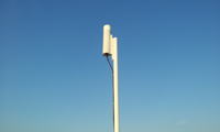
    A silicone tube, a stopper from the top for the deodorant and the bottom closure from the original "plunger" from the silicone tube. A 2.5-meter mast of PVC water pipe, all fixed on the roof of a two-story block. It perceives it better than the LONG WIRE which was before, mainly due to the lower amount of interference.

    Below is a typical converter circuit with a built-in, simple preamplifier.

    Link

    As for the disturbances, I fight them myself and there is something. What I did at the moment, apart from shielding the SDR receiver itself, I used a transformer power supply to power the laptop. It was impossible to work on the original one. He sowed mercilessly on all ranges.

    On the Internet, many people write about methods of fighting these disruptions:

    Link

    Here are some interesting comments - solutions, you need to scroll from 1/4 of the page:
    Link

    These SDR receivers are easy to overdrive with a strong signal, they have poor dynamics and you have to pay attention to it, because in this case terrible disturbances appear.
    I also recommend switchable bandpass filters if someone listens to amateur bands. The difference is very noticeable.

    best regards
  • #229 13632253
    mkpl
    Level 37  
    Maybe a colleague develop the topic of the MiniWhip antenna? It looks simple too simple to work and yet it works
  • #230 13632665
    methyl
    Level 16  
    Dear colleagues,
    I will not write about the antenna because others have already done it for me.
    In this article : Link there is a description of such an antenna. It's worth getting acquainted.

    The antenna works and it is not an "ordinary" wire with considerable amplification.
    Here the principle of operation is different.
    This small antenna, installed in the right place according to the rules, sometimes really gives better results than several dozen meters of wire.
    Interestingly, it receives from about 10-30kHz to 30MHz and some constructions that I have encountered can handle up to 160MHZ. I had a "Long Wire" type Antene stretched between the blocks and this 40m video I posted earlier is just listening on wire. This year I installed "Mini Whip" and I think I'll stay with it. At least to listen.


    The most known and used antenna at the moment is the "pa0rdt" version.
    I will provide some links to the construction.
    Link

    Link

    And constructions "improved" by subsequent designers:

    Link

    Link
  • #231 13635115
    mkpl
    Level 37  
    Disconnect tuner problem solved!
    Description of the problem: The tuner worked ok, but the HD SDR was freezing, there was a sound of disconnecting the usb, after a few attempts the system fixed and it displayed a message that the device can work faster, etc.

    Resoldering RT820 helped. This helped the disconnect effect when touching and bending the pcb.
    In addition, the tuner disconnected when moving it. I struggled with it for half a day and the problem turned out to be mundane. Poor usb plug. Soldering with the usb cable to the usb plug pads fixed the tuner 100%.

    Additionally, I measured the bone temperature. RTL 52 * C RT820 tuner over 60 * C and heats the entire pcb, including RTL, which causes a slight departure of the quartz generator frequency. You can see it nicely by observing the frequency of the converter and slightly blowing the pcb of the tuner
  • ADVERTISEMENT
  • #232 13636594
    methyl
    Level 16  
    Frequency drift is one of the negative effects of heating up the tuner electronics. The second thing to consider sometimes is noise increase.

    Here: Link
    There is a mention of this and a comparison of the noise of a heated and cooled tuner.


    I myself wonder if I should solder small heat sinks on the underside and sink it in a can of oil ;) How about a peltier module?
    Heating electronics is also a greater failure rate, silicon likes coolness :)

    But you can also like this:
    RTL-SDR - an SDR receiver from a cheap DVB-T tuner on a USB connector

    As for the frequency floating itself, those who bother it released quartz and replaced it with a temperature-stabilized generator. A cheap and effective solution
  • #233 13636615
    mkpl
    Level 37  
    With these noises it looks strange, as if the warmed up had jumped the gain because they only differ in signal strength.

    As for the oil and the fan, a stupid idea. It is easier to take a double-sided adhesive thermometer and stick the heat sink, such as to the RAM

    I wasn't talking about quartz in the converter (here I have a generator), but about a generator in the tuner.

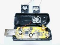
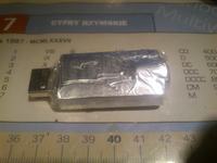
    As for the noise, I did it like in the picture below. I consider them sufficient and effective. The foil touches the ground with a USB connector and is additionally wrapped with transparent adhesive tape
    RTL-SDR - an SDR receiver from a cheap DVB-T tuner on a USB connector
  • #234 13637250
    methyl
    Level 16  
    I also talked about quartz in the tuner. Those who need stability install the TXCO there.

    Oil and fan it was just a joke. I also know more effective and simpler cooling solutions. The windmill would be even more stringy as it would generate a lot of interference by itself, especially so connected to the power supply from SDR.

    The main causes / sources of interference with reception are:

    - PC power supply, especially for laptops. It is easy to check this by listening to the band on the HF and switching to battery power in the process.

    -driven input of the SDR-RTL receiver. Between the output of the converter and the tuner it is worth to put an attenuator and preferably also a high-pass filter.

    -weak cables and no shielding. Lack of proper weight.
    It's also worth playing with the power supply. Power the converter from the akku. USB power is usually a tragedy. The power supply of the tuner should also be done separately from the computer.

    If someone listens to the HF, the preselector or bandpass filters are highly recommended.


    The difference with an unadjusted set and a "tuned" set to a minimum of distortions is huge. It's worth having fun! :)

    When I have a moment, maybe I will make a photo summary of the effects of improving, eliminating distortions.

    I am just researching the topic myself, reading and introducing changes. But I can see the effects, so I recommend it.
  • #235 13637265
    mkpl
    Level 37  
    I have a transformer power supply. I am constantly modifying the converter. Of course, the sheet metal housing (also diy :D ). In my free time, I will only change LA1185 to a diode mixer that I made and it lies and dusty.
  • #236 13637284
    methyl
    Level 16  
    I had to power the laptop from a transformer power supply, otherwise the chaff was amazing. Especially up to 8 MHz with max at 4 and 7 MHz.
    I did the converter on the diode mixer, but the NE612 was more comfortable for me.
    It is more sensitive and somehow cleaner during the listening session. I did the mixer myself on germanium diodes gd507 and appropriate ferrite cores, but it is possible that the factory class is silent ;)
  • #237 13637522
    lysy1980
    Level 33  
    As for the converter on a diode mixer, I did on the HPF-505 without a preamplifier, the better effect is on the LA .. TA .. I still have to try and do it on the NE612.
  • #238 13637557
    OK2STO
    Level 20  
    For Methyl, can you give a schema of this KF to SA612 (ne612) converter using a 50MHz generator, if you have checked that I would try it and I don't have to search on the net.
    Thanks Jarda
  • #239 13637741
    methyl
    Level 16  
    The easiest way is to do this and it will work ok:

    RTL-SDR - an SDR receiver from a cheap DVB-T tuner on a USB connector

    Better to give like this:

    RTL-SDR - an SDR receiver from a cheap DVB-T tuner on a USB connector

    And best as in the original:

    RTL-SDR - an SDR receiver from a cheap DVB-T tuner on a USB connector

    By putting an attenuator at the output of the converter, preferably in any of these cases.
  • #240 13637856
    OK2STO
    Level 20  
    Thanks for schematics.
    Will try.
    Jard

Topic summary

The discussion revolves around the use of RTL-SDR (Software Defined Radio) receivers, specifically utilizing inexpensive DVB-T tuners like the RTL2832U and R820T models. Users share experiences regarding the capabilities of these tuners to receive a wide range of frequencies, including AM, FM, and shortwave bands. Concerns about potential damage to the tuners when connecting antennas directly to the RTL2832 chip are raised, along with suggestions for protective measures such as using diodes. Various software options for SDR, including SDR# and HDSDR, are discussed, along with installation issues and driver compatibility. Users also explore antenna options, modifications for improved reception, and the effectiveness of different setups for receiving signals across various bands.
Summary generated by the language model.
ADVERTISEMENT