logo elektroda
logo elektroda
X
logo elektroda

LCR-T4 electronics components tester ATMega328 - Test and Review

TechEkspert 203976 647
ADVERTISEMENT
Treść została przetłumaczona polish » english Zobacz oryginalną wersję tematu
  • #601 19215289
    PiotrPitucha
    Level 34  
    Hello
    And the grounds loaded?
  • ADVERTISEMENT
  • #602 19215784
    Trabi
    Level 36  
    PiotrPitucha wrote:
    Hello
    And the grounds loaded?

    Yes. The last (E) for me was set - after reading it from the processor - on FD. Setting it to FC causes the T4 to not turn on at all or it turns on for a second, maybe two and goes out. FD and it works, except that it measures nothing (the LED sees for example as MOS-FET).
    LCR-T4 electronics components tester ATMega328 - Test and Reviewfuse.jpg Download (13.15 kB) LCR-T4 electronics components tester ATMega328 - Test and Reviewfuseok.jpg Download (13.15 kB)
    I log from programming:
    ~ ~ ~ ~ ~ ~ ~ ~ ~ ~ ~ ~ ~ ~ ~ ~
    >>>: avrdude -u -c usbasp -p m328p -P COM4 -B 0.5 -U flash:w:"C:\Users\User\Desktop\M328 firmware\m328.hex":a -U eeprom:w:"C:\Users\User\Desktop\M328 firmware\m328.eep":a -U lfuse:w:0xF7:m -U hfuse:w:0xD9:m -U efuse:w:0xFD:m 
    
    avrdude.exe: set SCK frequency to 1500000 Hz
    avrdude.exe: warning: cannot set sck period. please check for usbasp firmware update.
    avrdude.exe: AVR device initialized and ready to accept instructions
    
    Reading | ################################################## | 100% -0.00s
    
    avrdude.exe: Device signature = 0x1e950f (probably m328p)
    avrdude.exe: NOTE: "flash" memory has been specified, an erase cycle will be performed
                 To disable this feature, specify the -D option.
    avrdude.exe: erasing chip
    avrdude.exe: set SCK frequency to 1500000 Hz
    avrdude.exe: warning: cannot set sck period. please check for usbasp firmware update.
    avrdude.exe: reading input file "C:\Users\User\Desktop\M328 firmware\m328.hex"
    avrdude.exe: input file C:\Users\User\Desktop\M328 firmware\m328.hex auto detected as Intel Hex
    avrdude.exe: writing flash (24802 bytes):
    
    Writing | ################################################## | 100% 25.81s
    
    avrdude.exe: 24802 bytes of flash written
    avrdude.exe: verifying flash memory against C:\Users\User\Desktop\M328 firmware\m328.hex:
    avrdude.exe: load data flash data from input file C:\Users\User\Desktop\M328 firmware\m328.hex:
    avrdude.exe: input file C:\Users\User\Desktop\M328 firmware\m328.hex auto detected as Intel Hex
    avrdude.exe: input file C:\Users\User\Desktop\M328 firmware\m328.hex contains 24802 bytes
    avrdude.exe: reading on-chip flash data:
    
    Reading | ################################################## | 100% 12.77s
    
    avrdude.exe: verifying ...
    avrdude.exe: 24802 bytes of flash verified
    avrdude.exe: reading input file "C:\Users\User\Desktop\M328 firmware\m328.eep"
    avrdude.exe: input file C:\Users\User\Desktop\M328 firmware\m328.eep auto detected as Intel Hex
    avrdude.exe: writing eeprom (1024 bytes):
    
    Writing | ################################################## | 100% 10.91s
    
    avrdude.exe: 1024 bytes of eeprom written
    avrdude.exe: verifying eeprom memory against C:\Users\User\Desktop\M328 firmware\m328.eep:
    avrdude.exe: load data eeprom data from input file C:\Users\User\Desktop\M328 firmware\m328.eep:
    avrdude.exe: input file C:\Users\User\Desktop\M328 firmware\m328.eep auto detected as Intel Hex
    avrdude.exe: input file C:\Users\User\Desktop\M328 firmware\m328.eep contains 1024 bytes
    avrdude.exe: reading on-chip eeprom data:
    
    Reading | ################################################## | 100% 0.61s
    
    avrdude.exe: verifying ...
    avrdude.exe: 1024 bytes of eeprom verified
    avrdude.exe: reading input file "0xF7"
    avrdude.exe: writing lfuse (1 bytes):
    
    Writing | ################################################## | 100% 0.00s
    
    avrdude.exe: 1 bytes of lfuse written
    avrdude.exe: verifying lfuse memory against 0xF7:
    avrdude.exe: load data lfuse data from input file 0xF7:
    avrdude.exe: input file 0xF7 contains 1 bytes
    avrdude.exe: reading on-chip lfuse data:
    
    Reading | ################################################## | 100% 0.00s
    
    avrdude.exe: verifying ...
    avrdude.exe: 1 bytes of lfuse verified
    avrdude.exe: reading input file "0xD9"
    avrdude.exe: writing hfuse (1 bytes):
    
    Writing | ################################################## | 100% 0.00s
    
    avrdude.exe: 1 bytes of hfuse written
    avrdude.exe: verifying hfuse memory against 0xD9:
    avrdude.exe: load data hfuse data from input file 0xD9:
    avrdude.exe: input file 0xD9 contains 1 bytes
    avrdude.exe: reading on-chip hfuse data:
    
    Reading | ################################################## | 100% 0.00s
    
    avrdude.exe: verifying ...
    avrdude.exe: 1 bytes of hfuse verified
    avrdude.exe: reading input file "0xFD"
    avrdude.exe: writing efuse (1 bytes):
    
    Writing | ################################################## | 100% 0.02s
    
    avrdude.exe: 1 bytes of efuse written
    avrdude.exe: verifying efuse memory against 0xFD:
    avrdude.exe: load data efuse data from input file 0xFD:
    avrdude.exe: input file 0xFD contains 1 bytes
    avrdude.exe: reading on-chip efuse data:
    
    Reading | ################################################## | 100% 0.00s
    
    avrdude.exe: verifying ...
    avrdude.exe: 1 bytes of efuse verified
    
    avrdude.exe done.  Thank you.
  • ADVERTISEMENT
  • #603 19216456
    DJCheester
    Level 26  
    It is possible that I did not check the electrode software, so you say that you took the first steps ;) Bravo ;)
    Slingshot could fall, or actually measuring inputs from electrostatics, sometimes when you do not have the charges discharged from your hand, a spark jumps after touching the radiator - sometimes it could happen that you were holding an element and during checking, a charge could flow and damage the processor. And you have to remember about discharging the capacitors.

    Best regards...
  • #604 19217424
    Trabi
    Level 36  
    I think so, because something has been "loading" lately ;) and I did not put on the armband. Well, tomorrow I will try to replace it and reprogram it. I will let you know what and how if I manage to replace it, because I have never mentioned such babies :D .
  • #605 19217440
    DJCheester
    Level 26  
    Hey, it's not so terrible - flux and hot Air and a few seconds and the second one is on, I was also afraid of these SMDs until I got acquainted with the Hot Air station - now I can not imagine working without it - and I used to get tired of a soldering iron.

    I wish you success, let me know and good luck ;)
  • #606 19217967
    Trabi
    Level 36  
    And it went.

    There was a bit of tension because it was the first time I was dealing with this baby. There was no problem with desoldering, hot-air did its job. Then coffee (to calm your hands ;) ), flux, setting a new prock and soldering; it went without a problem. I downloaded the factory soft - and the tester started from the first inclusion. Calibrate and works as it worked :D .

    LCR-T4 electronics components tester ATMega328 - Test and Reviewpage.jpg Download (375.58 kB)

    Again, I want to thank you very much for your help.
  • #607 19220293
    DJCheester
    Level 26  
    Hello, whenever I replace the chip or other integrated circuit, where there are a lot of pins, I catch a new circuit using a soldering iron, external pins so that the system does not move and then I heat it - it guarantees that the system will not move and will not short-circuit. But the circuit is soldered very nicely and neatly for the first time - a big applause ;)

    I'm glad the hardware works ;)

    Best regards....
  • #608 19224855
    PiotrPitucha
    Level 34  
    Hello
    How you have a tolerable wind and not a storm :) it's not necessary to catch the butt. If you have a sensible paste or even well-tinned pads, the system will flow precisely to the center of the pads and so nicely that you won't be able to position it better by hand.
    Recently, I had a dense layout, almost twice as thick as the Atmega in the TQFP, and I will have to solder it that way. Generally, it is better to do it on a hob, but sometimes, due to the lack of systems, part of the testing system is mounted and there is no way to heat from the bottom.
    best regards
  • #609 19307536
    kristof_61
    Level 11  
    Hello.
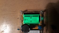
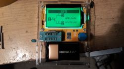
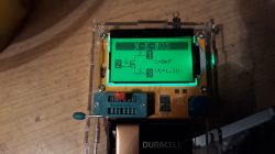
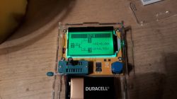
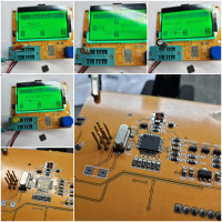
    Although I have a sticker on the housing "Discharge capacitor", I connected it without discharging and the display shows such pictures when measuring capacitors and resistors.
    LCR-T4 electronics components tester ATMega328 - Test and Review
    LCR-T4 electronics components tester ATMega328 - Test and Review LCR-T4 electronics components tester ATMega328 - Test and Review LCR-T4 electronics components tester ATMega328 - Test and Review
    In recent posts, you write that the processor may have crashed. Unfortunately, I will not replace the processor, let alone upload the software. I only have to buy a new tester.
  • #610 19307661
    DJCheester
    Level 26  
    Hello, it is possible that only the soft broke - before I started replacing it, you could connect to the programmer and try to upload the soft again.
    If you did not discharge the capacitor before the measurement, the processor could also ask what charge the capacitor could have - if the voltage on it was greater than 5V, you will probably have to replace the processor.

    Greetings ...
  • #611 19308320
    PiotrPitucha
    Level 34  
    Hello
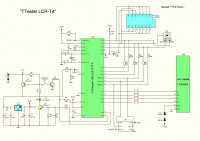
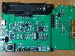
    Replacing the processor is a piece of cake, but you have to make your life easier. First of all, you gave a lot of photos and you can't see the processor on any of them, which is important for its replacement. Secondly, I can see that the GDPR is working :) , disappeared from the descriptions of the place of residence, and it may turn out that within a radius of several hundred meters you have someone who could help. You need to download a diagram to this meter and think what could shoot after turning on the charged capacitor. As the situation with the capacitor repeats itself, do not forget to share the damage in your case.
  • #612 19308511
    kristof_61
    Level 11  
    Hello.
    I'm going to watch it, I'll take some pics.

    Added after 1 [hours] 2 [minutes]:

    I read on the processor
    ATMEL
    MEGA328P
    U-TH
    35473D
    2007b3J
    Visually, no damage can be seen.
    I did the test without any element and it also shows interesting things.
    LCR-T4 electronics components tester ATMega328 - Test and Review LCR-T4 electronics components tester ATMega328 - Test and Review LCR-T4 electronics components tester ATMega328 - Test and Review LCR-T4 electronics components tester ATMega328 - Test and Review LCR-T4 electronics components tester ATMega328 - Test and Review LCR-T4 electronics components tester ATMega328 - Test and Review
  • ADVERTISEMENT
  • #614 19309182
    PiotrPitucha
    Level 34  
    Hello
    Now with photos and diagrams, there is clarity. At 99.9 & you beat the analog inputs in the processor.
    The matter is simple because next to the processor there is a lot of space and even with a soldering iron it can be repaired.
    Note the 6 pads stacked 2x3, this is definitely a place for the CANDA connector for programming
    processor, so you can connect the programmer without any excuses. You just need to see in what order
    There are pins to solder the socket from the right side.
    If you don't have a steady hand, every mobile and computer service will sell such a processor.
  • #615 19309569
    DJCheester
    Level 26  
    I already wrote about it right under the first pictures that the processor to replace - you need to buy a new "clean" chip (not programmed), then a soldering iron in your hand and after the replacement you need to program a new chip - more on this topic

    https://www.elektroda.pl/rtvforum/topic3372311.html

    The above-mentioned 2x3 pin connector is the KANDA connector in the picture below you can see exactly how to connect the signals for the KANDA connector.

    https://obrazki.elektroda.pl/1219969400_1503516373.jpg

    Photo not mine comes from the above-mentioned topic.

    Greetings ...
  • #616 19738890
    Dj Darecki
    Level 14  
    Welcome.
    And after a few years my M328 fell.
    I fired it without the element and suddenly the screen and crap went out.
    So after connecting to the power supply, it shows a consumption of about 250 mA, the screen does not light (sometimes blinks) the green LED.
    And the Atmel MEGA328P is heating up.
    It is a version for 14500 rechargeable battery and USB charging.
    Has it fallen?
  • #617 19738909
    AdamC
    Level 29  
    Dj Darecki wrote:
    Has it fallen?

    Hmm .. the glass ball does not respond to something.
    Then you have to grab a voltmeter and check the power path to the Atmel.
  • #618 19740394
    Dj Darecki
    Level 14  
    LCR-T4 electronics components tester ATMega328 - Test and Review After the measurements:
    Power supply on 4,6,18 feet. 3 volts at 4 volts battery voltage. There is also 3v on the feet under the charger

    Still backlighting the display, I see the inscription at startup:
    That the power supply is 7.5 volts OK (battery is about 4v)
    And then CELL pops up! and some mv and volt values are given
  • #619 19740412
    HD-VIDEO
    Level 43  
    Take a picture of the PCB to match some schematic, it will be easier
  • #620 19787700
    zepter
    Level 15  
    I tested a new purchase in the form of the LCR-TC2 tester. Everything was fine until the 22uf, 50V capacitor was inserted into the KAA sockets. Subject turned off. Thought the battery had run out. I connected to charging for an hour, but after turning it on again, this view appeared.
  • #621 19787717
    gumisie
    Level 43  
    zepter wrote:
    Everything was fine until the 22uf, 50V capacitor was inserted into the KAA sockets. Subject turned off
    The capacitor was discharged?
  • ADVERTISEMENT
  • #623 19787738
    Rezystor240
    Level 42  
    zepter wrote:
    No.


    Then you have the answer. Capacitors always discharge before measurement.
  • #624 19787742
    zepter
    Level 15  
    I know I made a mistake. But is it possible to test a discharged capacitor at KAA connectors?
    I would like to add that I tested the same capacitor on connectors 1-3 (several times) and it was OK, and when I put it into the KAA, the tester was damaged.
    Shouldn't it be damaged after inserting it into connectors 1-3 for the first time and not later in the KAA connector?
    I am asking because I would not like to damage the other one and know if it is possible to test other elements on the KAA connector.
  • #625 19787930
    darecki944
    Level 6  
    zepter wrote:
    No. But before that, I checked it on sockets 1-3 and it was OK.


    What are KAA connectors for?
    How to check the remote control code in this meter? I press the key on the remote control, the LED on the meter is blinking, but it shows nothing.
  • #626 19788746
    Ricoh_220

    Level 38  
    KAA is for measuring, for example, shorts and triacs
  • #627 19909884
    E8600
    Level 41  
    Has anyone checked whether LCR-T4 correctly recognizes naturally open field effect transistors (depletion mode)?
    I got the F501D and when testing with the multimeter it looks damaged (charging / discharging the gate does not change anything DS is constant voltage drop 0.4 V in both directions) and the tester correctly detects as ND-MOS but it does not show a parasitic diode?
    http://m.guangleitechnology.com/pd.jsp?pid=200
  • #628 20417287
    hrvojezd1968
    Level 2  
    I have two LCR T4 testers (no stripgrid) and I replaced the both ATmega328p... I tried all firmwares founded on the
    internet and always the capacitance measurement is not accurate. For example 4.7 microF shows 607nF on both pcb.
    I didn't write fuses & lock bits, only hex and eep files... I use extreme_burner_avr_v1.4.3 and avrdudeprog with usbasp.
    any idea please

    hrvoje

    edit: Lfuse: 0xF7, Hfuse: 0xD9, Efuse: 0xFC ... finally working fine :-)
  • #629 20418335
    Aress124
    Level 28  
    @hrvojezd1968 did you calibrate?
  • #630 20425161
    hrvojezd1968
    Level 2  
    Aress124 wrote:
    @hrvojezd1968 Have you calibrated?


    this is my first contact with programming...
    without a fuse the atmega clock is 1 mhz and this is a reason for measures a
    capacity 1/8 real value. after fuse set clock is 8 mhz and everything work fine.

    hrvoje

Topic summary

The discussion revolves around the LCR-T4 electronics components tester, which utilizes an ATMega328 microcontroller. Users share their experiences with the tester's capabilities, including automatic detection of component types, measurement of inductance, capacitance, and resistance, as well as calibration procedures. Concerns are raised about the accuracy of measurements, particularly with low inductance values and the tester's ability to identify certain components like transistors and diodes. Users also discuss the power supply options, including the use of 9V batteries versus rechargeable alternatives, and modifications to improve functionality. The conversation highlights the tester's utility for hobbyists and its limitations in professional applications.
Summary generated by the language model.
ADVERTISEMENT