logo elektroda
logo elektroda
X
logo elektroda

SOFAR 8kW PV Installation: Opinions, Durability, Failures & Experiences with Inverters

---Ryba--- 460113 1701
ADVERTISEMENT
Treść została przetłumaczona polish » english Zobacz oryginalną wersję tematu
  • #571 19393851
    toolpusher
    Level 23  
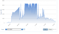
    I have recently enlarged the installation and gradually added panels - in our south there has not been a sunny day for several days. Here is a fragmented generator then had 5.44kWp. By the way, does downloading pictures from Solarman work? Because I have to do it via prtscreen. I don't know if chrome is blocking me or I can't download jpeg. Although the same on MS Edge.
  • ADVERTISEMENT
  • #572 19393861
    Janusz_kk
    Level 39  
    You can see the difference, so you've elegantly tuned the inverter :)
  • ADVERTISEMENT
  • #573 19393888
    toolpusher
    Level 23  
    :spoko: . 1 string on 2 MPPT in parallel mode. The interesting thing is that I was looking for the original MC4 Staubli tees but nowhere to find only the stiff ones. I have the original MC4 for the entire installation and I did not want to have Chinese at the inverter, so I was forced to do it myself. I clamp all the ends and solder additionally.
    All in all, it is strange that there are no original MC4 flex tees and I have written to several stores.
  • #574 19393892
    theo33
    Level 27  
    Saving jpeg doesn't work either, I copy similarly.
    I understand that you physically have the inputs connected in parallel and you also have the inputs set in parallel?
    Upload the graphs of voltages and currents
  • #575 19393904
    toolpusher
    Level 23  
    So I have switched in the inverter to parallel. I once corresponded with a serviceman from China regarding such a large oversizing of the installation and he told me to do it. Anyway, it was probably logical. I just wanted confirmation. For the readability of the chart, I only gave 1 string.
    I turned on the inverter late because I changed the jumper last night and wanted to be turned on. The best part was that at night I had nightmares that when turned on, the inverter went up in smoke :D
  • ADVERTISEMENT
  • #576 19393907
    theo33
    Level 27  
    These nightmares are uninteresting

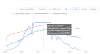
    And you can turn off the DC power and voltage from this diagram and turn on the pv1 and pv2 currents, if the current from the modules is divided equally on both inputs
  • ADVERTISEMENT
  • #577 19393913
    toolpusher
    Level 23  
    I also skimmed the report and so 99% is even, but sometimes there is a difference of 0.1A. There may also be rounding of values.
    I also have the impression that with 2x MPPT the inverter has become cooler.
  • #578 19393914
    theo33
    Level 27  
    As I thought, the module's current splits into two, here it comes out after about 4.5, so in my opinion the efficiency of the inverter will drop
    Why did you connect in parallel, since you have one string and most modules will not exceed 11A, unless you have modules with some higher current?
  • #579 19393926
    toolpusher
    Level 23  
    Because I have a 6.5kWp installation on a 4.4 inverter. The currents and voltages are normal, but the power is a bit too high, although it does not matter, because whether it cuts from 6.5kW or 5.0kW is probably the same.
    On the other hand, in this manual for installers, such connection is recommended - page 27 - Link

    What may the loss of fitness be? Looking at the graph, for example, the 600 and 800V curve is practically horizontal from 50% of the power.
  • #580 19394350
    prose
    Level 35  
    @toolpusher And the info menu should now be 5 kW
  • #581 19394413
    theo33
    Level 27  
    toolpusher wrote:
    Because I have a 6.5kWp installation on a 4.4 inverter. The currents and voltages are normal, but the power is a bit too high, although it does not matter, because whether it cuts from 6.5kW or 5.0kW is probably the same.
    On the other hand, in this manual for installers, such connection is recommended - page 27 - Link

    What may the loss of fitness be? Looking at the graph, for example, the 600 and 800V curve is practically horizontal from 50% of the power.


    The decrease in efficiency on weakly loaded inputs may be some, but probably negligible and if the graph relates to the AC output power, it is flat from 35%, but if it was also related to the power of the inputs, the load up to 3A at the input, i.e. up to 30%, would be losses. to be.
    In my opinion, this parallel connection applies to strings connected in parallel when the summed current exceeds the capacity of the inverter input, while in your case it does not change anything, the previous limitation to 4.4 results from the output power after AC.
    Once upon a time I made such attempts that I physically connected the inputs in parallel, but I left the settings independent and the current was distributed randomly, and in my opinion it was a result of the mppt algorithm because they will never work identically. And it looked like that with low powers one input worked, and with higher powers both. Unfortunately, I can't track these charts right now
  • #582 19394439
    Cytro12
    Level 26  
    The graph grows up to 50% and again decreases towards 100% load, I note that the given graph is for a high power inverter there is probably 12kW, the smaller the inverter, the lower the efficiency, but generally the characteristics match (similar components and algorithms). Fronius has a little different again for an example of a different solution. We take into account the point at which the inverter has been operating the longest, not the extreme conditions.

    The independent work of MPPT here depends on the speed of the processor and the quality of the algorithm.
  • #584 19394750
    prose
    Level 35  
    Now just check that the temperature doesn't go too high.
  • #585 19394769
    toolpusher
    Level 23  
    Well, it seems to me that it has become cooler, but it is probably because 2 MPPT work but with less load. Besides, if it is the same inverter up to 6.6, I think it will be fine at 5.5.
  • #586 19394802
    prose
    Level 35  
    toolpusher wrote:
    Well, it seems to me that it has become cooler, but it is probably because 2 MPPT work but with less load. Besides, if it is the same inverter up to 6.6, I think it will be fine at 5.5.

    It got colder because you split the load equally on the MPPT inputs, 5.5 ktlx reaches the temperature at full power 50 degrees.
  • #587 19394818
    toolpusher
    Level 23  
    I wonder if this module temperature is not a detector on the heat sink. Because in my case, the heat sink at 50st the inverter is slightly warm and now it's even summer.
  • #588 19394911
    prose
    Level 35  
    From what I was able to find out the module is the IGBT AC temperature on the heat sink.
  • #589 19395585
    toolpusher
    Level 23  
    theo33 wrote:
    toolpusher wrote:
    Because I have a 6.5kWp installation on a 4.4 inverter. The currents and voltages are normal, but the power is a bit too high, although it does not matter, because whether it cuts from 6.5kW or 5.0kW is probably the same.
    On the other hand, in this manual for installers, such connection is recommended - page 27 - Link

    What may the loss of fitness be? Looking at the graph, for example, the 600 and 800V curve is practically horizontal from 50% of the power.


    The decrease in efficiency on weakly loaded inputs may be some, but probably negligible and if the graph relates to the AC output power, it is flat from 35%, but if it was also related to the power of the inputs, the load up to 3A at the input, i.e. up to 30%, would be losses. to be.
    In my opinion, this parallel connection applies to strings connected in parallel when the summed current exceeds the capacity of the inverter input, while in your case it does not change anything, the previous limitation to 4.4 results from the output power after AC.
    Once upon a time I made such attempts that I physically connected the inputs in parallel, but I left the settings independent and the current was distributed randomly, and in my opinion it was a result of the mppt algorithm because they will never work identically. And it looked like that with low powers one input worked, and with higher powers both. Unfortunately, I can't track these charts right now


    Ok then I'll go back to 1 MPPT. If it is actually one inverter for the 3.3-6.6 range, then it should support power up to 6250Wp per MPPT according to the card without any problem. As a colleague Cytro12 wrote, most of the time the inverter does not work at full power, hence there may be large drops in efficiency for 2 x MPPT.

    Added after 2 [minutes]:

    Cytro12 wrote:
    The graph grows up to 50% and again decreases towards 100% load, I note that the given graph is for a high power inverter there is probably 12kW, the smaller the inverter, the lower the efficiency, but generally the characteristics match (similar components and algorithms). Fronius has a little different again for an example of a different solution. We take into account the point at which the inverter has been operating the longest, not the extreme conditions.

    The independent work of MPPT here depends on the speed of the processor and the quality of the algorithm.


    I have not seen another chart, it is only the one for the 11KTL-X. Additionally, I found that in some manuals for KTL-X three-phase inverters there was a graph for single-phase TL series where the last curve was for 500V.
  • #590 19396742
    adamvfr
    Level 11  
    Is it normal that the current is always lower in the PV2 string by about 0.5A
    Hello, Sofar 3.68KTLM Panels 2 strings, 8 pcs each, the same.
    For a few days I had only 7 panels plugged in the string PV2 and looking at the statistics I had better production with seven than when I plugged in the eighth one. Maybe this is a margin of error, but I certainly did not notice an increase in prod. rather a reduction (I have a comparison to an adjacent installation). Mathematically, I got about 4% less total production after plugging in the eighth module.
  • #591 19396797
    Janusz_kk
    Level 39  
    You may have a partially damaged panel and therefore have more production without it, or it is shaded which gives the same effect.
  • #592 19396800
    toolpusher
    Level 23  
    What version of Solarman are these charts from?
  • #593 19396817
    theo33
    Level 27  
    These charts show that you already have 8 modules here, show the charts from 7 where the production was higher and compare which parameter made it worse.
    Also, swap the inputs because the input algorithms are not the same, and if the situation changes, it could be considered that the strings differ, maybe in length, lighting, I think that the parameters of the modules do not differ?
  • #594 19397503
    adamvfr
    Level 11  
    Charts from Solarman Smart.
    The thongs are identical, no shade.
    I have analyzed these charts in more detail, I can also give the login and password to someone who is insightful, because I would like to understand it better myself.
    So you can see the difference in Amps even when there were 7 panels, but in the peaks it is much smaller then.
    At least that's how I see it.
    On the third day of operation of this installation, the allegedly low V grid and frequency was turned off (see diagram below), but the inverter did not turn on by itself, so I turned off DC and AC and fired and started normally.
    Two days later (also the graph) the inverter recorded zero DC and AC voltages too! but it did not turn off, why?
  • #596 19397541
    theo33
    Level 27  
    Drop on private. this access and enter the page, I can browse.
    And as I wrote before, swap the inputs
  • #597 19397698
    Cytro12
    Level 26  
    If you have a clamp meter, check the actual values on the cables, because these measurements of these inverters are of different quality. If Sofar has different algorithms for MPPT, this equipment is weak because they say that there are two independent MPPTs and it turns out that there is one and the other as a divisor because the inputs are too weak.
    I wonder if this equipment will last at least until the end of the warranty :)

    It would be a pity because they put it en masse into every cheap installation.
  • #598 19397809
    Janusz_kk
    Level 39  
    Cytro12 wrote:
    If Sofar has different algorithms for MPPT, this equipment is weak because they say that there are two independent MPPTs and it turns out that there is one and the other as a divisor because the inputs are too weak.

    Can you write something closer?
  • #599 19397831
    adamvfr
    Level 11  
    I would also read. So every 2 thongs but basically one? artificially divided?
  • #600 19397890
    prose
    Level 35  
    ZdzislawDyrmaZasadni wrote:
    Hello, I have a general attention to SOFAR inverters. According to in the current manual, these inverters must not be installed in basements or any other low-lying rooms, because min. the required distance from the ceiling must be 80 cm.
    If someone has to buy Chinese, better choose SOLAX.

    And solax does not need ventilation?

Topic summary

The discussion centers on experiences with Sofar inverters in approximately 8kW photovoltaic (PV) installations, focusing on technical issues, durability, and configuration challenges. Users report generally stable operation with models like Sofar 6.6KTL-X and 5.5KTL-X over extended periods, though some face connectivity problems, especially with Wi-Fi and software availability. A recurring technical problem involves input voltage exceeding the maximum allowed 600V DC for single-phase Sofar inverters (notably the 4KTLM-G2), causing errors such as PVOVP and BusOPV and inverter shutdowns. This is often due to too many PV panels connected in series on a single string, with 15 Q.CELLS Q.PEAK G4.1 305W panels sometimes exceeding voltage limits, especially in cold conditions where voltage rises. Solutions include splitting panels into two strings (e.g., 8 and 7 panels) connected to separate MPPT inputs, though some users report this does not fully resolve the issue. The maximum recommended panels per MPPT input is around 9 to avoid surpassing power and voltage limits. Users also discuss the need for three-phase inverters for larger installations above 7kW on a single phase due to grid operator restrictions. Software and firmware updates are sought after but not easily accessible, with some users lacking Polish language support. Comparisons with other brands like SMA and Fronius highlight Sofar's cost advantage but raise concerns about long-term reliability and service support, which is still developing in some regions. Network-related errors such as Grid OFP (over-frequency) have been reported, with troubleshooting involving network frequency checks and inverter restarts. Overall, Sofar inverters are considered a cost-effective option with some technical caveats related to system design, installation quality, and support infrastructure.
Summary generated by the language model.
ADVERTISEMENT