logo elektroda
logo elektroda
X
logo elektroda

T.amp TSA 4-1300 Power Amplifier Issue: Not Turning On, Red Diode Flashing, No Visible Damage

Matek920605 69333 346
ADVERTISEMENT
Treść została przetłumaczona polish » english Zobacz oryginalną wersję tematu
  • #151 18506293
    ziro_9
    Level 10  
    Hello,
    kudlatyy1 wrote:
    I gave up, I bought two-channel modules from the Chinese, two pieces, 60v power supply and 300w power

    I understand that you are going to develop the T.AMP housing with new guts. You need to plan the layout of the modules well to make the most of the airflow.

    kudlatyy1 wrote:
    and now the question is, is a 1500 watt converter enough?

    What are these modules? Give them a name so we can find out more about them.
    When selecting a switching power supply, you need to take into account:
    - the efficiency of the amplifier
    - maximum load

    Regards.
  • ADVERTISEMENT
  • ADVERTISEMENT
  • #153 18506451
    ziro_9
    Level 10  
    Hello,
    kudlatyy1 wrote:
    Class AB tip

    So yeah.
    Let's assume an efficiency of 60% (maybe 50%)
    4 channels driven = 1200W RMS
    1200 / 0.60 = 2000W
    The inverter must have a minimum power of 2kW
    If you choose a good 2kW inverter, you must provide it with very good cooling.
    Of course, the inverter is not equal to the inverter and you can come across the overrated "Chinese" who has 2kW in the description, and in fact barely 1kW.
    Regards.
  • #154 18506480
    kudlatyy1
    Level 12  
    Thanks to ziro, I know that with these powers it is different, I'm still looking.
  • #155 18539907
    rzepong
    Level 7  
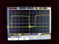
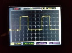
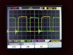
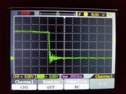
    Gentlemen, you rummage around this amplifier, I got rid of the damage to a final degree, everything on the secondary power supply. I took out the main transformer to eliminate the possibility of a short circuit on the secondary side in the tip. The problem is with the hot converter, the keying transistors and the ir2110s control chips are constantly sitting down. I removed the transistors and their control circuits and checked with the oscilloscope what is fed to the "Hin" and "Lin" inputs of the ir2110s. The signal from the "A" output of the SG3525 is elegantly square, while the "B" output is bouncing at the falling edge. Could this cause the keying transistors to open slightly, shorting the + to - bus?
    I have no ideas where to look for the problem. The problem is evident on the hot side, but all the resistors, zeners, diodes replaced and measured, the auxiliary converter is working properly, ne555, lm339 also replaced. I enclose the mileage measurement (the one that raises my doubts in green).
    T.amp TSA 4-1300 Power Amplifier Issue: Not Turning On, Red Diode Flashing, No Visible Damage T.amp TSA 4-1300 Power Amplifier Issue: Not Turning On, Red Diode Flashing, No Visible Damage T.amp TSA 4-1300 Power Amplifier Issue: Not Turning On, Red Diode Flashing, No Visible Damage T.amp TSA 4-1300 Power Amplifier Issue: Not Turning On, Red Diode Flashing, No Visible Damage
  • ADVERTISEMENT
  • #156 18542909
    Anonymous
    Level 1  
  • #157 18543291
    Krzychu1843
    Level 12  
    I would recommend checking if the capacitors and resistors responsible for the "discharge" of the IGBTs are working. On the pcb they have the designation C180, R467, C179, R466 etc. I got rid of one pair of transistors at the beginning of the repairs just because one of these capacitors was released.
    If any of you have this amplifier on the table, I would have a small request. I need to know the value of the capacitor at sg3525a marked C196. My meter shows 390pF and this is inconsistent with what you can read in the datasheet for the system.
  • #158 18546380
    rzepong
    Level 7  
    I changed the sg3525 and the problem to determine, Is anyone able to measure the capacitance of the ceramic capacitors of the high side bootstrap ir2110? (3 capacitors in parallel, one of them is c209, you can measure the capacitance on it).
    In one driver the bootstrap has 3.3 uF, in the other 2.6 uF. Could the reduced capacity of the bootstrap cause incomplete opening of the transistor and large heat losses on it, which causes it to burn quickly?
    @Krzychu ;) are you able to give me the correct value of these IGBT discharge capacitors? On Tuesday / Wednesday I will be there, I will check the capacitor you are asking for.
  • #159 18546766
    Krzychu1843
    Level 12  
    I used 150pF at 1kV - of course it is enough to give 500 but just 1kV are more easily available. As for the bootstrap, from what I remember (unfortunately I do not have an amplifier on hand so I can be wrong) it was a 1206 1uF ceramic capacitor - 3 connected in parallel, as you say, i.e. within 3uF. Both drivers are symmetrically made to each other, so there should not be such a difference - I don't know how much charge these capacitors give off during discharge - maybe 0.7uF determines whether the driver will maintain the IGBT state or not. It is safest to replace it with a minimum of 3uF. In total, if we collect the values of individual elements, we could think about creating a spreadsheet file that would facilitate further repairs.
  • ADVERTISEMENT
  • #160 18574805
    aaanteka
    Level 42  
    Krzychu1843 wrote:
    If any of you have this amplifier on the table, I would have a small request. I need to know the value of the capacitor at sg3525a marked C196. My meter shows 390pF and this is inconsistent with what you can read in the catalog note of the system

    And here we come to the merits of the case. Probably the manufacturer used a version of the system dedicated to him, because the system has been produced in a dozen or so companies over the years and as a property it was also sold to competitors on the production market several times. In addition, there are licensed products with the same or similar designation. Despite this, the old catalog notes from the time of paper catalogs from the 1980s and 1990s are still widely available today. In addition, the system was produced in various versions, including military and professional industrial ones. It is a fact that the available catalog note in many production executions does not fully reflect the applied R, C values of the generator, and dead time, and yet such systems work properly and sometimes for decades.
    It remains to check the practical frequency of work, the dead time for the entire implementation system and the selection of elements.
    In our serviced amplifiers, the value of the Ct capacitor (up to pin 5) was different for individual units from different production periods. Usually these values were: 330,390,420,430pF (measured with a laboratory bridge at a measuring frequency from 1kHz to 1MHz). Similarly with the 470-620 ohm dead time resistor.

    rzepong wrote:
    In one driver the bootstrap has 3.3 uF, in the other 2.6 uF. Could the reduced capacity of the bootstrap cause incomplete opening of the transistor and large heat losses on it, which causes it to burn quickly?

    Basic knowledge, what is the purpose of bootstrapping and how does it work? What might a capacity deviation indicate?
    A good rule of thumb in the event of damage to such elements as IGBT drivers is to replace all elements that work directly with the damaged system. Prophylactically.
    Krzychu1843 wrote:
    In total, if we collect the values of individual elements, we could think about creating a spreadsheet file that would facilitate further repairs.

    The only thing is that those who can fix it right away have been on the market for years, and the product is already slightly old and has a shameful history among users. Hardly any serious acoustician, sound director or even a DJ decides to repair this amplifier, let's add a costly repair. If someone tries to repair this equipment based on commonly available components in the retail trade for a total amount of less than 1/2 of the market value of this amplifier, he is hoeed to the sun and is incorrect optimists. For this reason, we gave up in my company. But I don't want to confuse you, it's all ahead of you, colleagues.
  • #161 18598770
    rzepong
    Level 7  
    I was able to get this converter on my feet. In my case, the damage was quite extensive, but there were no burned paths or broken chips.
    First, the BTA41-600B triac on AC power (located on a small heat sink) flew for replacement,
    Then removing all damaged elements: 4 IGBT, 2 IR2110, SG3525, LM339, Diodes and resistors on IGBT gates, the entire auxiliary converter system (+ 15V).
    In general, the process of replacing these elements mentioned in previous posts, in my case, the bootstrap capacitors on the IGBT drivers were an additional problem, after their replacement and increasing the bootstrap capacity to 4uF, the converter gets up. I am left with the assembly of power amplifier blocks (there were probably 8 power transistors burned in them, all the control ones survived). From the further start-up, I will report how the amplifier comes to life.
  • #162 18600563
    aaanteka
    Level 42  
    rzepong wrote:
    increasing the bootstrap capacity to 4uF the inverter gets up.

    What kind of capacity did you put in?

    What are your current voltages on individual power lines? Have you checked the inverter on an artificial load?
    rzepong wrote:
    First, the BTA41-600B triac on the AC power supply flew for replacement (located on a small heat sink)

    The bridge rectifier on the network side is not damaged? With such extensive overloads, it is better to replace it, because it was certainly overloaded temporarily.
    Generally, this amplifier has this feature that when something breaks down, practically 80-90% of the power elements (dealing with the power flow) flies :) ) therefore it seems most reasonable to list all the elements, even those that have survived (they can be used in less sensitive structures). There is no risk of risking it, the more so that the failure of the four-channel amplifier complicates the issue of the sound system (greater reliability is required).

    What's more, subsequent damage to the amplifier with incomplete replacement of elements can be more extensive.
    It is worth making the owner aware of this: - one more cost (say 1.3-1.5 times the incomplete one) or 2-3 costs of incomplete repairs within the next year?
    Simple arithmetic for everyone :D .
  • #163 18601560
    rzepong
    Level 7  
    @aaanteka
    4 ceramic capacitors 50V / 1uF. As for the bridge, he survived, and the triac behaved weird during the test: one way it kept the conduction state after the signal loss on the gate until the voltage dropped to 0, while in the opposite direction it would keep conduction, but it also faded out. right after the signal disappeared at the gate, so I preferred to replace it.

    After starting the amplifier with the main luck, instead of the artificial load, the oscilloscope was clamped only on the low voltage winding, there is 17VAC. Faulty did not want to go down, and you can clearly hear the converter, quick measurement of DC voltage at the output of the power amplifiers: 8V ... Removal of the output transistors including power bus switching transistors, then more op-amps, then 8V at the output.
    This DC voltage remains the same for each of the 4 channels, interestingly even behind the relays that are normally open, and the control does not activate them, so it's very strange ... Anyway, I will have a little digging in this invention.
    Maybe someone has any suggestions for this DC output voltage?
  • #164 18605877
    INtRO_Tech
    Level 14  
    Rzepong, look for my post on this topic regarding the connection of ground points on the motherboard removed from the case, without it everything will go crazy.

    Regards
  • #165 18625482
    popej
    Level 13  
    was it launched by someone with one channel desoldered? because I do not know if the fan controller is going crazy or something else because the hurricane is made after a minute of starting, unless it is because instead of IRGP4066d I put IXXH100N60B3 in the converters
  • #166 18625496
    INtRO_Tech
    Level 14  
    Hello, it shouldn't be like that.

    This is not a question of IRGP replacements.

    I fired with one removed channel, but nothing went crazy except the LED from the clip on the removed channel. Solder the temperature sensor into the removed channel because it was probably on the heat sinks and therefore it is at maximum speed.

    Regards
  • #167 18625506
    Krzychu1843
    Level 12  
    Check the voltages on the NTCs for all channels plus the inverter. Maybe one of them is banged up or got damaged while removing the heat sinks.
  • #168 18625585
    popej
    Level 13  
    Well, there are no two at all because I took out the entire pnp / npn rails together with them so as not to pick out this glue
  • #169 18625680
    Krzychu1843
    Level 12  
    Well, you already know the answer :)
  • #170 18625699
    popej
    Level 13  
    and someone will tell you if this gp105n15m is 150v / 120a / 8.8mohm? and what to replace it with? because I put the converters together but I did not measure everything in the ends and I still miss this mosfet to finally put it together
  • #171 18625745
    Krzychu1843
    Level 12  
    I will not let my head cut off because I am also just looking for a replacement for it, but the AOT2500L caught my eye.
  • #172 18625757
    popej
    Level 13  
    well, rds the price too, but 107a I found IPP051N15N5AKSA1 only the price does not suit me a bit :D
  • #173 18625775
    Krzychu1843
    Level 12  
    107Amps, yes, but the original at the same temperature (100 degrees) is 85A, so there is nothing to be afraid of. There is everything in the catalog note :)
  • #175 18626401
    ziro_9
    Level 10  
    Hello,
    Such a curiosity.
    The newer 1737 version uses IXTP56N15T mosfets. The substitutes that you wrote about will be good.
    Regards
  • #176 18626527
    Szymek11211
    Level 11  
    Hello. This tip also fell into my hands, after a day of measurements and replacements, the converter got up. The listed SG3535, IR2110, NE555, Zenerkas on the gates, 1n4148 diodes on the gates, viper22 and several diodes within it, 47R gate resistors. So far I ran it on IRGP4068 because I had them, do you think that they are interchangeable? Because, unfortunately, I found 2 different datasheets and their parameters.

    For me, the bootstrap at IRs has not equal values, equalize them, or if the inverter works well for now, leave it on low powers?
  • #177 18626601
    popej
    Level 13  
    IRGP4068 and not boiling it? after all, they are 2 times weaker, now that's 1/3 of the planned performance
  • #178 18626654
    Szymek11211
    Level 11  
    popej wrote:
    IRGP4068 and not boiling it? after all, they are 2 times weaker, now that's 1/3 of the planned performance


    So far, tested on low power, they will eventually enter 4066 then
  • #179 18626704
    popej
    Level 13  
    and tell me you have a patent for these je..ne clamps? on taking off putting on? because it irritated me so much that I drilled the heat sinks and screwed everything up the old way
  • #180 18626818
    Szymek11211
    Level 11  
    popej wrote:
    and tell me you have a patent for these je..ne clamps? on taking off putting on? because it irritated me so much that I drilled the heat sinks and screwed everything up the old way


    I would also like to know about some normal method, because I took 2 flat screwdrivers and bent this plate and somehow slipped each of the transistors under it.

Topic summary

The discussion revolves around issues with the T.amp TSA 4-1300 power amplifier, specifically its failure to turn on, indicated by a flashing red diode and no visible damage. Users share their experiences troubleshooting the amplifier, including checking the power supply, replacing damaged components like IGBTs, IR2110 drivers, and capacitors, and the challenges of finding schematics. The conversation highlights the importance of proper voltage levels, the need for fuses to prevent damage, and the potential for modifications to improve reliability. Several users report successful repairs after replacing critical components and adjusting the power supply configuration.
Summary generated by the language model.
ADVERTISEMENT