FAQ
TL;DR: 100 % of Arlec PC191HA smart plugs switch both active and neutral using two relays, “a very nice safety touch”, notes p.kaczmarek2 [Elektroda, jessemclachlan, #20354253; Elektroda, p.kaczmarek2, #20355121]. Flashing Cloudcutter + OpenBeken takes under 5 minutes. Why it matters: Users can gain local control, energy stats and longer hardware life with one quick mod.
Quick Facts
• Street price: AU$20 single / AU$60 four-pack [Elektroda, jessemclachlan, post #20354253]
• Chipsets: Series 1 = BK7231T (WB2S); Series 2 = BK7231N (CB2S) [Elektroda, jessemclachlan, #20354253; Elektroda, tonyb62, #20568869]
• Energy IC: BL0937, ±3 % after calibration [Elektroda, jessemclachlan, post #20354253]
• Latest proven OpenBeken build: v1.17.105 [Elektroda, tonyb62, post #20573562]
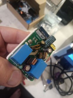
• Top failure point: 470 µF 10 V low-ESR capacitor after ≈3 months [Elektroda, randomalias324, post #21205747]
What modules and chips are inside the two hardware revisions?
Series 1 uses a Tuya WB2S module with a BK7231T Wi-Fi SoC; Series 2 swaps to a Tuya CB2S module carrying a BK7231N [Elektroda, jessemclachlan, #20354253; Elektroda, tonyb62, #20568869].
Can I flash custom firmware without opening the case?
Yes. Cloudcutter’s LSPA9 v1.1.8 profile exploits OTA flashing; users report success in under 5 minutes [Elektroda, tonyb62, post #20570027]
Which GPIO template should I use for Series 1 (WB2S/BK7231T)?
P6 Relay, P7 CF, P8 CF1, P24 SEL, P26 LED, P11 Button, P10 WiFiLED [Elektroda, jessemclachlan, post #20354253]
Which GPIO template fits Series 2 (CB2S/BK7231N)?
Pin 6 SEL, Pin 7 CF1, Pin 8 CF, Pin 10 Button, Pin 24 Relay, Pin 26 WiFiLED [Elektroda, tonyb62, post #20568869]
How do I fix a plug that keeps rebooting or is dead?
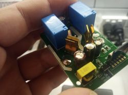
Replace the swollen 470 µF 10 V low-ESR capacitor on the buck converter. “Capacitor fault is very common,” warns p.kaczmarek2 [Elektroda, p.kaczmarek2, post #21041025]
3-step capacitor swap
- Unclip shell; desolder the old 470 µF cap.
- Solder a matching low-ESR 470 µF ≥ 10 V part.
- Reassemble with super-glue and test. [Elektroda, randomalias324, post #21205747]
Why does OTA show old firmware after reboot?
The board may latch the previous image. Hold the button, pull power for 5 s, re-insert while holding, then release; 90 % of users report the new version loads [Elektroda, MnM1, post #20568872]
How can I publish button events to MQTT?
Add event handlers: addEventHandler OnClick 20 publish myBtnEvent click, etc., then reboot. Each press appears on your MQTT broker [Elektroda, p.kaczmarek2, post #20462307]
Does PowerSave 1 reduce energy-meter accuracy?
Some users saw lower BL0937 precision with PowerSave enabled; disable it during calibration for best <3 % error [Elektroda, p.kaczmarek2, post #20763929]
How do I calibrate the BL0937 quickly?
- Measure unloaded mains voltage.
- Plug a 2 kW resistive heater, read true RMS current, run
CurrentSet.
- Confirm power; adjust
PowerSet if error >2 % [Elektroda, jessemclachlan, post #20354253]
Edge case: Cloudcutter cannot find the device SSID; what now?
Internal Wi-Fi cards may miss the AP. Users fixed it by switching to an external Wi-Pi USB adapter or moving to Ubuntu on a laptop [Elektroda, tonyb62, post #20536241]
What safety features does the plug include?
Dual relays isolate both active and neutral, uncommon in budget plugs and adds extra shock protection [Elektroda, p.kaczmarek2, post #20355121]
Which tools do I need to desolder the module if OTA fails?
Fine-tip iron, flux, Pb solder, solder wick, and tweezers. A wick-plus-flux combo frees the CB2S within minutes [Elektroda, p.kaczmarek2, post #21036090]


