logo elektroda
logo elektroda
X
logo elektroda

4-in-1 temperature, humidity, luminosity wifi sensor and clock NEO NAS-TH02 NAS-CW01W6

gilles_m 2181 4

TL;DR LABEL_AI_GENERATED

  • NEO NAS-TH02 NAS-CW01W6 is a 4-in-1 WiFi sensor for temperature, humidity, luminosity, and clock/date through Tuya Smartlife.
  • A ZigBee version also exists, but this WiFi model adds the practical clock and date display.
  • Inside, the main wireless controller is a bk7231n chip providing WiFi and Bluetooth services.
  • The case has no screws and relies on plastic and glue, and removing the board requires unsoldering the four battery connectors.
AI summary based on the discussion. May contain errors.
ADVERTISEMENT
Listen:
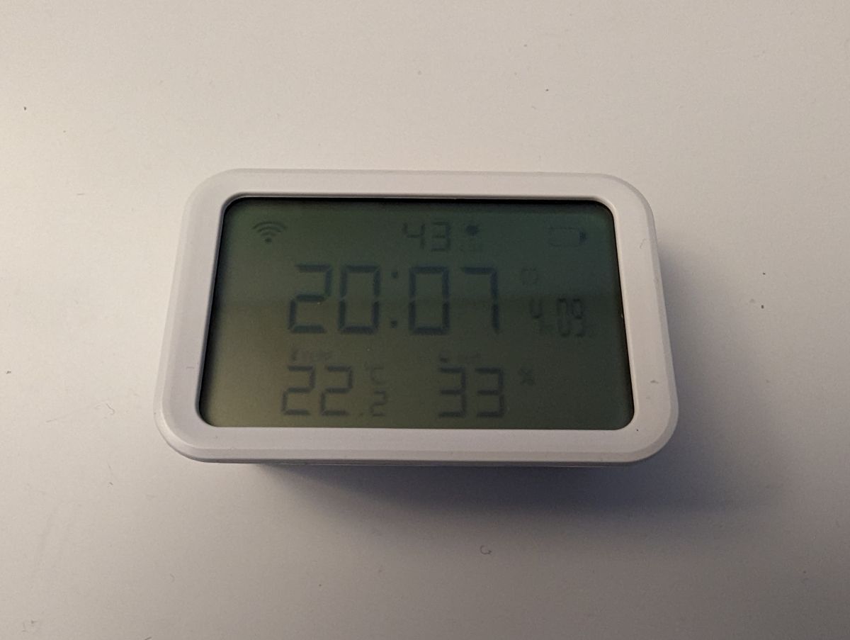
  • This is the teardown of a device providing temperature, humidity and luminosity information through Tuya Smartlife, with Wifi. Another version exists with ZigBee protocol.
    This wifi version also provides a clock and date, which is quite practical.

    Here is a review of the ZigBee version (without the clock) :
    https://www.lesalexiens.fr/labo-test-alexa/te...-capteur-zigbee-simple-complet-et-polyvalent/

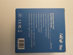
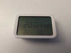
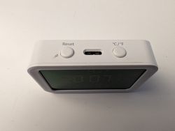
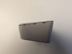
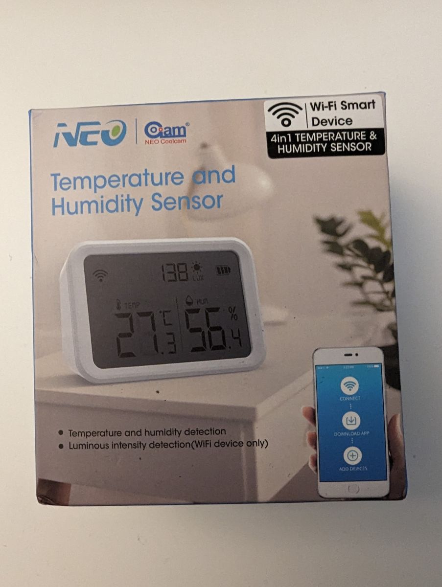
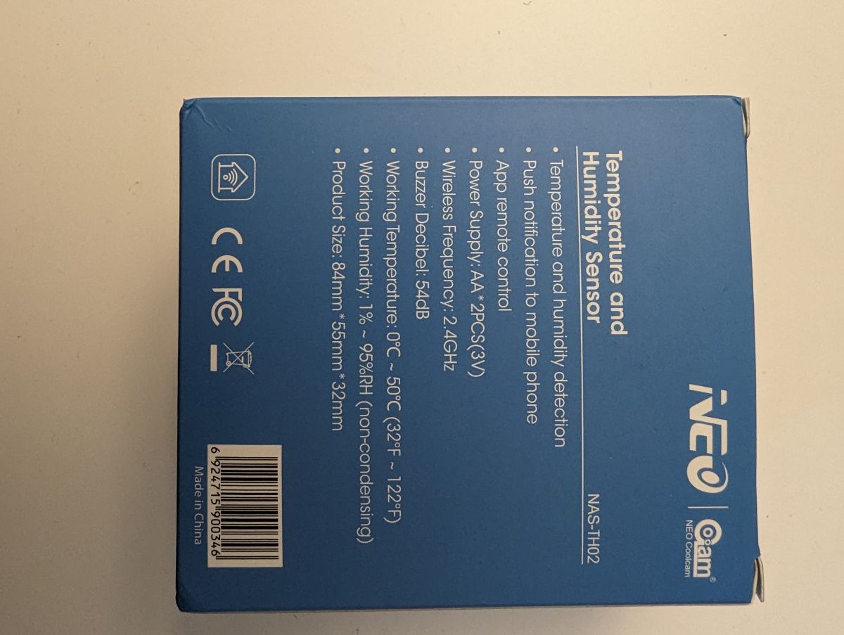
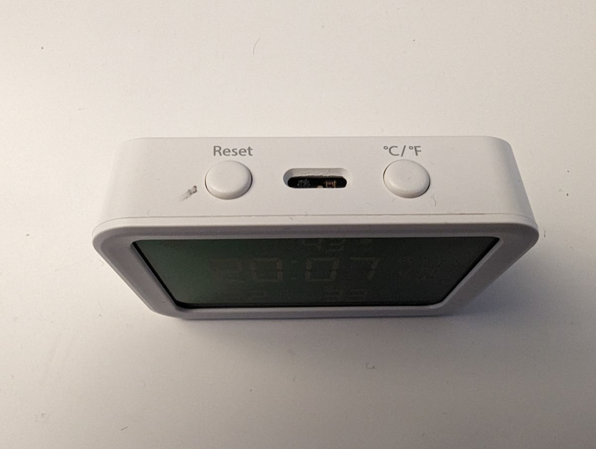
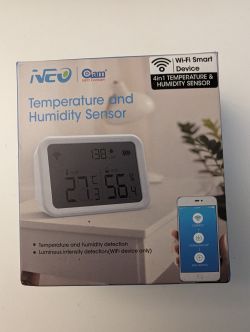
    Here are photos of the packaging:
    4-in-1 temperature, humidity, luminosity wifi sensor and clock NEO NAS-TH02 NAS-CW01W6

    4-in-1 temperature, humidity, luminosity wifi sensor and clock NEO NAS-TH02 NAS-CW01W6

    4-in-1 temperature, humidity, luminosity wifi sensor and clock NEO NAS-TH02 NAS-CW01W6

    4-in-1 temperature, humidity, luminosity wifi sensor and clock NEO NAS-TH02 NAS-CW01W6

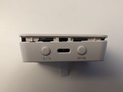
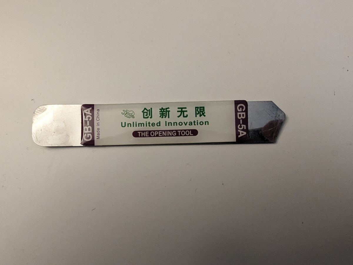
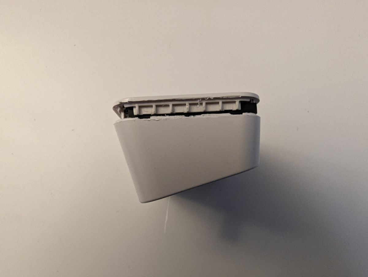
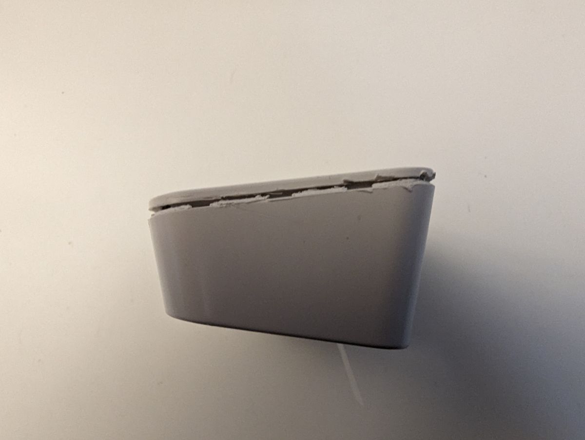
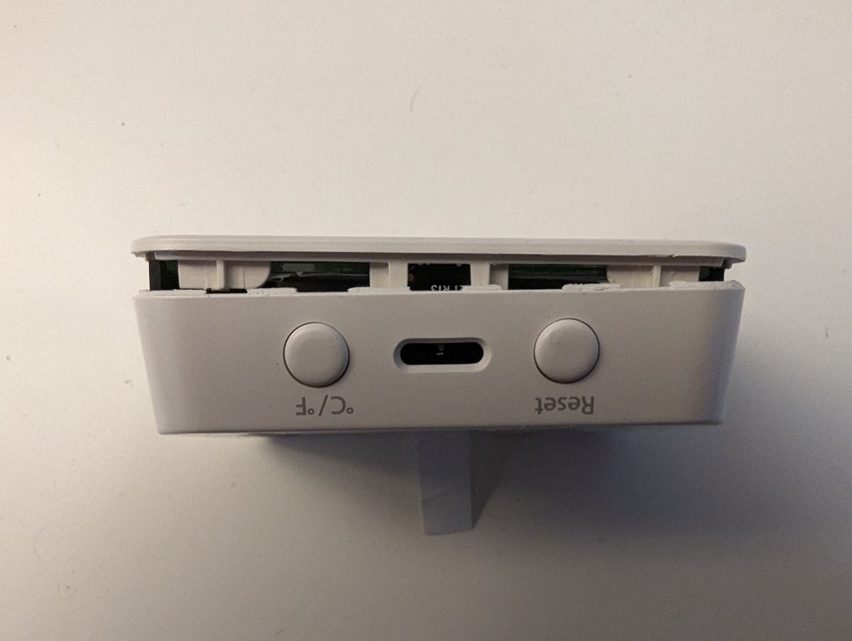
    To open it, there are no screw, only plastic and glue. I've opened it only with the following opening tool.
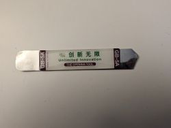
    4-in-1 temperature, humidity, luminosity wifi sensor and clock NEO NAS-TH02 NAS-CW01W6

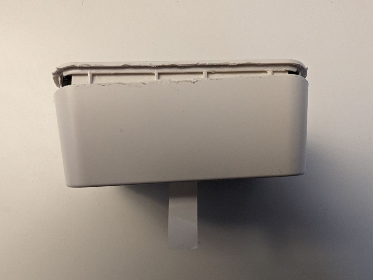
    I had to force it quite a lot at the bottom and on the left and right sides. Be careful with the top side, as there's the connector going to the screen.
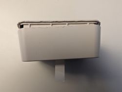
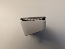
    4-in-1 temperature, humidity, luminosity wifi sensor and clock NEO NAS-TH02 NAS-CW01W6

    4-in-1 temperature, humidity, luminosity wifi sensor and clock NEO NAS-TH02 NAS-CW01W6

    4-in-1 temperature, humidity, luminosity wifi sensor and clock NEO NAS-TH02 NAS-CW01W6

    4-in-1 temperature, humidity, luminosity wifi sensor and clock NEO NAS-TH02 NAS-CW01W6

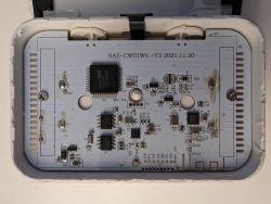
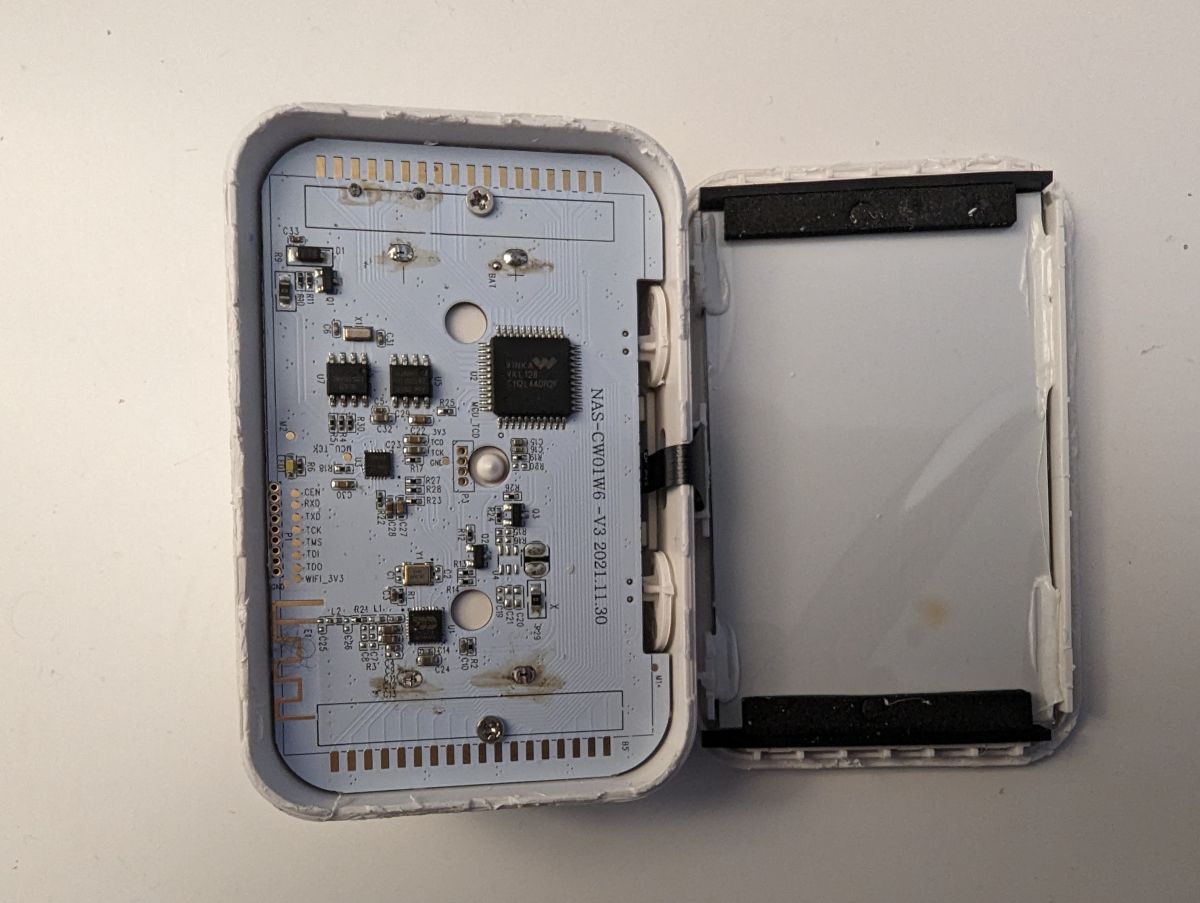
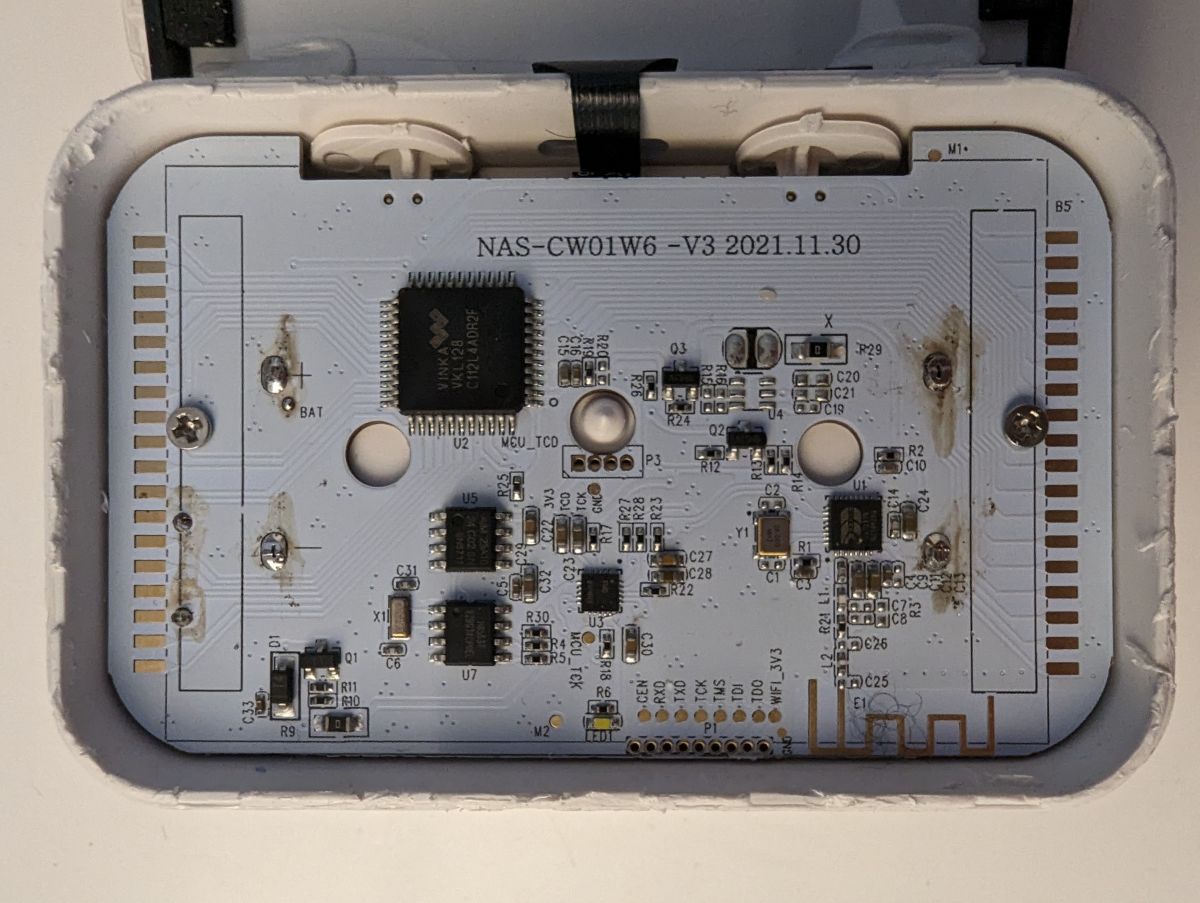
    Here is the result once it's open.
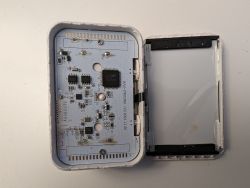
    4-in-1 temperature, humidity, luminosity wifi sensor and clock NEO NAS-TH02 NAS-CW01W6

    4-in-1 temperature, humidity, luminosity wifi sensor and clock NEO NAS-TH02 NAS-CW01W6

    One can see that this device uses a bk7231n chip to provide Wifi and bluetooth services.

    If one wants to remove completely the board, one has to unsolder the 4 connectors linked to the batteries.

    Cool? Ranking DIY
    About Author
    gilles_m
    Level 2  
    Offline 
    gilles_m wrote 2 posts with rating 2, helped 1 times. Been with us since 2023 year.
  • ADVERTISEMENT
  • #2 20534190
    p.kaczmarek2
    Moderator Smart Home
    Posts: 14795
    Help: 659
    Rate: 12953
    Looks like a TuyaMCU device. Doing a packet capture now would certainly help in further configuration:
    TuyaMCU analyzer - UART packet decoder for Tuya devices - dpID detector
    Helpful post? Buy me a coffee.
  • ADVERTISEMENT
  • Bypass fried BK7231N with ESP module wiring

    #3 20547510
    gilles_m
    Level 2  
    Posts: 2
    Help: 1
    Rate: 2
    Hello,
    I wish I could do what you suggest, but unfortunately I have fried the bk7231n chip by applying by mistake a 5V voltage. All the rest of the device is working well.

    So my first step would be to "replace" the bk7231n, but as one can see, it's not possible to simply remplace a little board. Would you have suggestions on how to bypass the bk7231n, and solder a TYWE3S/ESP12 (or is it another module that should be used) with cables? I guess I would have to break traces to the current bk7231n, but also I have no clue about what to solder to what. I can solder, but I'm not really aware of the functionning of such a board, so I would need guidance.

    Best regards
  • ADVERTISEMENT
  • #4 20550921
    tonyb62
    Level 8  
    Posts: 37
    Help: 1
    Rate: 3
    you can probably buy the chip but do you know someone with smd soldering experience?

    Then you will still have to buy a second device to capture the original firmware from it too.
  • #5 20551605
    p.kaczmarek2
    Moderator Smart Home
    Posts: 14795
    Help: 659
    Rate: 12953
    It is relatively hard to replace chip in QFN package, but it's definitely possible.

    It may be also hard to solder ESP12F in that device, is there even a place for that on the board? I don't think so. BK7231 is there directly on PCB.
    Helpful post? Buy me a coffee.
Listen:

FAQ LABEL_AI_GENERATED

TL;DR: This 4-in-1 NEO NAS-TH02 / NAS-CW01W6 WiFi FAQ, with the expert warning "no screw", helps repairers open the glued Tuya Smart Life sensor, identify the BK7231N, and avoid damaging the screen connector or PCB. [#20532431] Why it matters: The device combines sensing, display, WiFi, Bluetooth, batteries, and glued plastic, so one wrong voltage or pry point can turn a teardown into a repair job.

Alternative Protocol / platform Clock/date display Thread-relevant repair note
NEO NAS-TH02 / NAS-CW01W6 WiFi WiFi through Tuya Smart Life Yes Uses a BK7231N directly on the PCB
NAS-TH02B ZigBee version ZigBee No Mentioned as a separate version reviewed externally
TYWE3S / ESP12 / ESP12F idea ESP8266-class replacement concept Not confirmed Space and wiring are unresolved

Key insight: The BK7231N is not a plug-in module here; it sits directly on the PCB. Replacing or bypassing it needs board-level work, not a simple module swap.

Quick Facts

  • The WiFi version reports temperature, humidity, and luminosity through Tuya Smart Life, and also shows clock and date. [#20532431]
  • The enclosure has no screws; it uses plastic clips and glue, with the screen connector located near the top side. [#20532431]
  • Full PCB removal requires unsoldering 4 battery-linked connectors from the board. [#20532431]
  • Applying 5V by mistake fried the BK7231N while the rest of the device still worked. [#20547510]
  • The repair discussion compares 3 replacement paths: BK7231N chip replacement, ESP12F wiring, and TYWE3S/ESP12 wiring. [#20547510]

How do you open the NEO NAS-TH02 / NAS-CW01W6 WiFi temperature, humidity, luminosity sensor and clock without damaging the screen connector?

Open it with a thin plastic opening tool, not a screwdriver. The case has no screws, only plastic and glue. Work hardest at the bottom, left, and right sides. Avoid forcing the top edge because the screen connector sits there.
  1. Insert a plastic opener at the bottom.
  2. Release the left and right sides.
  3. Lift the top carefully after the case separates. [#20532431]

What components are inside the NEO NAS-TH02 WiFi sensor, and where is the BK7231N chip located?

Inside are the display assembly, main PCB, battery connections, and a BK7231N chip on the board. The WiFi version provides temperature, humidity, luminosity, clock, and date functions. The author reports that the BK7231N provides WiFi and Bluetooth services. It is mounted directly on the PCB, not on a removable daughterboard. [#20532431]

What is a BK7231N chip, and what role does it play in Tuya Smart Life WiFi sensors?

"BK7231N is an onboard wireless microcontroller chip that provides WiFi and Bluetooth services, mounted directly on the PCB in this device." In the NEO NAS-TH02 WiFi sensor, it links the sensor functions to Tuya Smart Life connectivity. The thread shows it as the central wireless part, not as a small replaceable module. [#20532431]

What is a TuyaMCU device, and why might the NEO NAS-TH02 be identified as one?

"TuyaMCU is a Tuya device architecture that uses UART packets between a wireless chip and another controller, enabling datapoint-based control and reporting." The NEO NAS-TH02 looked like a TuyaMCU device to the forum expert. He suggested a packet capture to support later configuration. That comment came on 2023-04-11. [#20534190]

How can a UART packet capture help configure a TuyaMCU-based temperature and humidity sensor?

A UART packet capture can reveal the datapoints needed for further configuration. The expert specifically said that doing a packet capture would help. In this context, the capture targets TuyaMCU traffic. It can show which dpID values represent temperature, humidity, luminosity, or other displayed data. [#20534190]

What is the TuyaMCU analyzer and how does it detect dpID values in Tuya devices?

"TuyaMCU analyzer is a UART packet decoder for Tuya devices that helps detect dpID values from captured serial communication." The linked tool title describes it as a TuyaMCU analyzer, UART packet decoder, and dpID detector. The forum expert recommended it after identifying the sensor as likely TuyaMCU. [#20534190]

How can I bypass a fried BK7231N chip in a NEO NAS-TH02 and wire in a TYWE3S, ESP12, or ESP12F module?

The thread does not provide a verified wiring map for bypassing the fried BK7231N. The owner asked about TYWE3S, ESP12, and ESP12F after applying 5V by mistake. The expert warned that ESP12F installation may be hard because the BK7231N is directly on the PCB. Space on the board was also questioned. [#20551605]

What traces or connections would need to be modified when replacing the onboard BK7231N with an ESP8266 module?

The thread does not identify exact traces or pin-to-pin connections for an ESP8266 replacement. The owner expected trace cutting because the original BK7231N remained on the PCB. He also said he had no clear soldering map. No later post supplies a confirmed connection table for TYWE3S, ESP12, or ESP12F. [#20547510]

What happens if 5V is accidentally applied to a BK7231N chip in a battery-powered Tuya sensor?

Applying 5V can fry the BK7231N chip. The owner reported this exact failure after a mistaken 5V connection. He also reported that the rest of the device still worked. This is the thread’s clearest failure case and the reason for discussing chip replacement or bypass wiring. [#20547510]

How difficult is it to replace a BK7231N chip in a QFN package on the original PCB?

Replacing the BK7231N is relatively hard because the chip uses a QFN package. The expert still said it is definitely possible. This means the job needs board-level rework skill, not ordinary through-hole soldering. The difficulty also increases because the chip is mounted directly on the original PCB. [#20551605]

What tools and skills are needed for SMD soldering a replacement BK7231N chip?

You need SMD soldering experience to replace the BK7231N safely. One commenter asked whether the owner knew someone with that experience. The expert later identified the package as QFN, which makes alignment and heating harder. The thread does not list exact tools, so it only supports the required skill level. [#20550921]

Why might buying a second NEO NAS-TH02 device be necessary before replacing the damaged BK7231N chip?

A second device may be needed to capture the original firmware. One commenter said the owner would still need a second device for that purpose after buying a replacement chip. The damaged unit had a fried BK7231N, so it could not serve as a reliable firmware source. This advice appeared on 2023-04-22. [#20550921]

BK7231N vs ESP12F vs TYWE3S: which module is most suitable for repairing or converting a Tuya WiFi sensor?

The thread supports BK7231N replacement as the most direct repair path, but not the easiest soldering job. ESP12F, TYWE3S, and ESP12 were only proposed as bypass ideas. The expert questioned whether ESP12F would physically fit. He also noted that the original BK7231N is directly on the PCB, not on a module. [#20551605]

What is the difference between the WiFi NEO NAS-TH02 / NAS-CW01W6 sensor with clock and the ZigBee NAS-TH02B version without clock?

The WiFi version works through Tuya Smart Life and includes a clock and date display. The ZigBee version exists as another model and lacks the clock, according to the teardown author. The WiFi unit also uses a BK7231N for WiFi and Bluetooth services. The ZigBee version was only referenced through an external review link. [#20532431]

How can I safely remove the PCB from the NEO NAS-TH02 when the battery connectors are soldered to the board?

Remove the PCB only after unsoldering the 4 connectors linked to the batteries. The author states this is required to remove the board completely. Do not pull the PCB while those connectors remain attached. That can stress the battery wiring, pads, or nearby display connection. [#20532431]
AI summary based on the discussion. May contain errors.
ADVERTISEMENT