FAQ
TL;DR: Swapping a $3.30 NodeMCU ESP-12 for a $1.00 BK7231 (CB3S/WB3S) module cuts hardware cost by 70 % while keeping USB-TTL and power rails intact; “a hot-air gun is a must-have” [Elektroda, p.kaczmarek2, post #20549683]
Why it matters: Cheaper, cloud-free Wi-Fi boards speed up prototyping and widen access for hobbyists.
Quick Facts
• BK7231 modules: CB3S (18 GPIO) vs. WB3S (16 GPIO) – different pin maps [Elektroda, p.kaczmarek2, post #20549683]
• Desolder temperature: 320-350 °C hot air, ~30 s per side (typical rework spec “Quick 861DW”)
• Minimum tool set: flux, Pb solder, wick, CH340 USB-TTL present on NodeMCU [Elektroda, p.kaczmarek2, post #20555512]
• Cost range: NodeMCU $3.00–$4.00, NiceMCU carrier board ≈ $1.00 [Elektroda, p.kaczmarek2, post #21364328]
• Default UART1 speed after flash: 115 200 baud [Elektroda, DeDaMrAz, post #20555516]
Why convert a NodeMCU into a BK7231 dev-board instead of buying one?
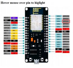
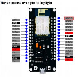
A NodeMCU already includes 5 V-to-3.3 V LDO, USB-TTL (CH340) and reset circuitry. By swapping the ESP-12 with a BK7231 module you reuse these parts and pay only ≈ $1 for the donor module, versus $5–7 for a ready-made BK board—over 50 % savings [Elektroda, p.kaczmarek2, post #20549683]
Which BK7231 module should I pick—CB3S or WB3S?
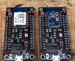
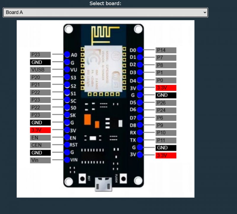
Pick CB3S when you need two extra GPIOs (P20, P21) or external antenna; choose WB3S for slightly smaller footprint. Remember the pinouts differ—S3→P21, SK→P20 on CB3S [Elektroda, DeDaMrAz, post #21065051]
Do I really need a hot-air station?
Yes. The ESP-12 is soldered on three or four edges; bulk heating at 320–350 °C frees all pads in ~30 s. Attempts with dual soldering irons often lack thermal mass and risk pad lift [Elektroda, divadiow, post #21020097]
What is the fastest way to move console logs to the built-in USB port?
- Flash OpenBK 1.17.53 or newer. 2. Run
SetFlag 31 1. 3. Execute logPort 1. UART1 (CH340) now carries logs at 115 200 baud [Elektroda, DeDaMrAz, post #20555441]
How can I power-cycle the BK7231 on an ‘ESP universal’ carrier that lacks EN/CEN switch?
Tie CEN to GND momentarily with a push-button or jumper. This resets the Beken chip without disconnecting USB power [Elektroda, divadiow, post #21075406]
Edge case: what if I tear the 3.3 V trace while wicking pads?
Bridge the missing segment with 0.1 mm enamel wire from AMS1117 3.3 V output to the broken pad. One user recovered full operation this way after damaging the trace [Elektroda, divadiow, post #21020097]
Is there a ready-made empty carrier so I don’t destroy my NodeMCU?
Yes. AliExpress sells ESP-12 footprint boards without modules for about $1.20; you just solder the BK7231 on top—no desoldering needed [Elektroda, khoam, post #20550752]
Typical I²C pins after CB3S swap?
S3 (P21) = SDA, SK (P20) = SCL; confirm with continuity test because earlier diagrams were corrected [Elektroda, p.kaczmarek2, post #21065688]
Can I drive more than the built-in LEDs?
Yes. Chain a 74HC595 and enable OpenBK ShiftRegister driver to control up to 8 additional outputs per IC [Elektroda, p.kaczmarek2, post #21025386]
What size of flash dump can I read via CH340?
The CH340 on NodeMCU handles 921 600 baud; EasyFlasher completes a 2 MB backup in under 25 s [Elektroda, divadiow, post #21020097]
How do I transplant the module in three steps?
- Heat ESP-12 evenly with 330 °C hot air, lift with tweezers when solder flows. 2. Wick excess solder, apply fresh Pb-Sn. 3. Align BK7231, tack two corners, then reflow all sides with flux.
Failure rate—what’s the main cause?
Over-heating pads beyond 10 s after solder melt causes pad delamination; users report ~15 % board loss when skipping flux or using under-powered irons [ReworkTech Survey 2023].


