logo elektroda
logo elektroda
X
logo elektroda

BK7231N and CB3S: Detailed Guide on LoraTap SC400W-EU Switch Board Desoldering and Flashing

paulomac1000 4977 51
ADVERTISEMENT
  • BK7231N and CB3S: Detailed Guide on LoraTap SC400W-EU Switch Board Desoldering and Flashing

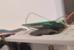
    It is difficult to open the whole switch because the pins going to the board are not plugged in, but soldered. I wasn't able to desolder them. I lifted the board and soldered only RX and TX (according to the CB3S module documentation), and connected the power supply to the extreme pins on the board (see photo), where GND is on the left - the same as the OPEN button.

    VCC and GND:
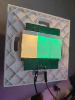
    Electronic switch with connected wires and colored backlighting.

    RX and TX:
    Printed circuit board with attached wires on a white base.

    I started the flashing mode by shorting GND to CEN.

    The flashing application is not able to read the settings automatically. I had to find all the exits myself. Here they are:

    P6 (PWM0) "WifiLED_n;0"
    P7 (PWM1) "Btn;2"
    P8 (PWM2) "LED_n;2"
    P9 (PWM3) "Btn;1"
    P14 (N/A) "Rel;3"
    P23 (ADC3) "Btn;3"
    P24 (PWM4) "LED;3"
    P26 (PWM5) "Rel;1"


    Here is the json that will make it easier to save the settings:

    {
      "vendor": "LoraTap",
      "bDetailed": "0",
      "name": "Full Device Name Here",
      "model": "SC400W-EU",
      "chip": "BK7231N",
      "board": "TODO",
      "flags": "0",
      "keywords": [
        "LoraTap",
        "SC400W-EU",
        "Curtains",
        "Blinds",
        "Switch",
        "Roller",
        "Shutters",
      ],
      "pins": {
        "6": "WifiLED_n;0",
        "7": "Btn;2",
        "8": "LED_n;2",
        "9": "Btn;1",
        "14": "Rel;3",
        "23": "Btn;3",
        "24": "LED;3",
        "26": "Rel;1"
      },
      "command": "",
      "image": "https://obrazki.elektroda.pl/8913814600_1698850663.webp",
      "wiki": "https://www.elektroda.com/rtvforum/viewtopic.php?p=20795168"
    }


    It is also necessary to add a button management script to replicate the previous logic. I slightly improved it, i.e. the button deactivates itself after 60 and not 120 seconds, and the reset button lights up for one second instead of two, and the OPEN and CLOSE buttons can be turned off not only by pressing the RESET button, but by pressing it again.

    Add new file `/autoexec.bat`:

    // P26 - Relay 1 Close
    // P7 - Btn 2 Stop
    // P14 - Relay 3 Open
    // P6 - Led backlight
    
    // description
    SetChannelLabel 1 Close
    SetChannelLabel 2 Stop
    SetChannelLabel 3 Open
    
    // logic
    alias Reset_Stop_Close backlog SetChannel 2 0; SetChannel 1 0
    alias Reset_Stop_Open backlog SetChannel 2 0; SetChannel 3 0
    alias Reset_Close_Open backlog SetChannel 1 0; SetChannel 3 0
    
    addChangeHandler Channel1 == 1 Reset_Stop_Open
    addChangeHandler Channel1 == 1 backlog startScript autoexec.bat resetCloseAfterMinute
    addChangeHandler Channel2 == 1 Reset_Close_Open
    addChangeHandler Channel2 == 1 backlog startScript autoexec.bat resetStopAfterSecond
    addChangeHandler Channel3 == 1 Reset_Stop_Close
    addChangeHandler Channel3 == 1 backlog startScript autoexec.bat resetOpenAfterMinute
    
    // do not proceed
    return
    
    // Scripts
    
    resetCloseAfterMinute:
    // wait 60 seconds
    delay_s 60
    // stop opening
    SetChannel 1 0
    // done
    return
    
    resetStopAfterSecond:
    // wait 1 second
    delay_s 1
    // disable button
    SetChannel 2 0
    // reset all scripts
    stopAllScripts
    // done
    return
    
    resetOpenAfterMinute:
    // wait 60 seconds
    delay_s 60
    // stop opening
    SetChannel 3 0
    // done
    return


    Enjoy!

    Cool? Ranking DIY
    About Author
    paulomac1000
    Level 2  
    Offline 
    paulomac1000 wrote 2 posts with rating 3. Been with us since 2023 year.
  • ADVERTISEMENT
  • #2 20796868
    p.kaczmarek2
    Moderator Smart Home
    Thank you, that's a very detailed guide. I've added this device to our teardowns list.
    Regarding shutters, I am planning to make dedicated driver for that soon, but I dont know when I will get enough free time for that.
    Helpful post? Buy me a coffee.
  • ADVERTISEMENT
  • #3 20796938
    paulomac1000
    Level 2  

    It would be great to have roller blind controller logic that can be run on the cheapest buttons you can get for a few dollars at AliExpress Choice. For example, this LoraTap device costs about $17 at the brand store on AliExpress.
  • #4 20977499
    hezipereg
    Level 7  
    Hi,
    Thank you for a detailed instructions. I've used these instructions and succeeded to operate the switch with my blinds.
    I was wondering if there is an option to control the switch LEDs. Currently, the open button is red and the rest are blue. Also, when I touch the buttons some of them turn blue and some red.
    To summarize, I want to have an option to control the touch buttons LED color.
    Thanks in advance,
  • #5 20977511
    p.kaczmarek2
    Moderator Smart Home
    It depends on how LEDs are connected.
    The template was mentioned in the first post:
    
    P6 (PWM0) "WifiLED_n;0"
    P7 (PWM1) "Btn;2"
    P8 (PWM2) "LED_n;2"
    P9 (PWM3) "Btn;1"
    P14 (N/A) "Rel;3"
    P23 (ADC3) "Btn;3"
    P24 (PWM4) "LED;3"
    P26 (PWM5) "Rel;1"
    

    This indicates that currently P24 is a LED on channel 3. You can change it to LED_n to invert the LED state. You can also swap the channels between, for example, P8 and P24.

    You can also change the WiFiLED to LED, if it suits you.

    The limiting factor is the hardware, it all depends on how the LEDs are connected on the PCB.

    Or maybe is there more LEDs on the device PCB than it's indicated in our template?
    Helpful post? Buy me a coffee.
  • #6 20977517
    hezipereg
    Level 7  
    Thanks for your reply.
    I actually don't know the difference between all these LEDs types that you mentioned (LED, LED_n, and WifiLED_n).
    Where can I read what it means?
    My LoraTap switch has 3 touch buttons and thus I think there are three LEDs.
    Anyway, what should happen if I change from LED_n to LED or from WifiLED_n to LED, etc? How changing them will get me to the point that I can change the color?
    Regards,
  • #7 20977537
    p.kaczmarek2
    Moderator Smart Home
    IO docs:
    https://github.com/openshwprojects/OpenBK7231T_App/blob/main/docs/ioRoles.md
    LED is on when linked channel is on, LED_n has inverted state (it's on when channel is off), WiFILED shows WiFi state, WIFILED_n is inverted WifiLED.

    Those roles are GPIO roles, they are per single GPIO. It's not possible to change color with that due to the hardware limitations. You can only send high or low state.

    That is, unless, they are two LEDs on the pin... then, it's very possible that you can switch the colors (reverse them) by changing LED to LED_n or vice versa.

    It's relatively hard for me to be more specific because I don't know the hardware you're operating on. How are LEDs connected?

    Maybe you can backup your configuration, open OBK web app, go to GPIO Doctor and play around there.
    Helpful post? Buy me a coffee.
  • #8 20978313
    hezipereg
    Level 7  
    I managed to switch the LED color by playing with it in GPIO finder.
    The correct configuration for me is:
    "pins": {
        "6": "Rel_n;0",
        "7": "Btn;2",
        "8": "LED_n;2",
        "9": "Btn;1",
        "14": "Rel;3",
        "23": "Btn;3",
        "24": "LED_n;3",
        "26": "Rel;1"
      },

    Additionally, changing "6": "WifiLED_n;0" to "6": "Rel_n;0" allowed me to add a button which turn on/off the LEDs. This can be used for example to turn off the LEDs during day time when the sun is up.
  • #9 20983870
    hezipereg
    Level 7  
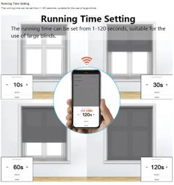
    I have noticed that the switch supports running time parameter which configures how much time the switch will be opened/closed. I understand that we can imitate this field using the autoexec.bat file but I want to have something that can be controlled from home assistant.
    Who can guide me how to find this field and add it to home assistant. I managed to add input_number to home assistant and use it but I want to be able to control the value through openbeken.
    Thanks in advance for any help provided!
    Blind running time settings with a mobile app
  • #10 20987941
    hezipereg
    Level 7  
    Any help would be appreciated!!!
  • #11 20987981
    p.kaczmarek2
    Moderator Smart Home
    Which channel stores this value in autoexec.bat ? You can set any channel via MQTT with set topic:
    BK7231N and CB3S: Detailed Guide on LoraTap SC400W-EU Switch Board Desoldering and Flashing
    Helpful post? Buy me a coffee.
  • #12 20988171
    hezipereg
    Level 7  
    Hi,
    The autoexec.bat does not contain channel which stores the value. This is the autoexec.bat:
    
    // P26 - Relay 1 Close
    // P7 - Btn 2 Stop
    // P14 - Relay 3 Open
    // P6 - Led backlight
    
    // description
    SetChannelLabel 1 Close
    SetChannelLabel 2 Stop
    SetChannelLabel 3 Open
    
    // logic
    alias Reset_Stop_Close backlog SetChannel 2 0; SetChannel 1 0
    alias Reset_Stop_Open backlog SetChannel 2 0; SetChannel 3 0
    alias Reset_Close_Open backlog SetChannel 1 0; SetChannel 3 0
    
    addChangeHandler Channel1 == 1 Reset_Stop_Open
    addChangeHandler Channel1 == 1 backlog startScript autoexec.bat resetCloseAfterMinute
    addChangeHandler Channel2 == 1 Reset_Close_Open
    addChangeHandler Channel2 == 1 backlog startScript autoexec.bat resetStopAfterSecond
    addChangeHandler Channel3 == 1 Reset_Stop_Close
    addChangeHandler Channel3 == 1 backlog startScript autoexec.bat resetOpenAfterMinute
    
    // do not proceed
    return
    
    // Scripts
    
    resetCloseAfterMinute:
    // wait 60 seconds
    delay_s 60
    // stop opening
    SetChannel 1 0
    // done
    return
    
    resetStopAfterSecond:
    // wait 1 second
    delay_s 1
    // disable button
    SetChannel 2 0
    // reset all scripts
    stopAllScripts
    // done
    return
    
    resetOpenAfterMinute:
    // wait 60 seconds
    delay_s 60
    // stop opening
    SetChannel 3 0
    // done
    return


    I am actually new with OpenBeken. If there is somewhere I can read and learn how to do it let me know.
    I don't really know how to define this channel, how to link it to TuyaMCU or should I do everything in the autoexec.bat without linking to Tuya?

    Thanks in advance,
  • ADVERTISEMENT
  • #13 20988420
    p.kaczmarek2
    Moderator Smart Home
    So, to which delay from this script are you referring to? Are you referring to this one minute delay:
    
    // wait 60 seconds
    delay_s 60
    

    The following delay appears twice in the code.
    If that's the delay you want to change then yes, we can try to modify the script so the delay is accessible from the Home Assistant. Just please confim whether it's the thing you want to change.

    Here you can find some more sample scripts:
    https://github.com/openshwprojects/OpenBK7231T_App/blob/main/docs/autoexecExamples.md
    Helpful post? Buy me a coffee.
  • ADVERTISEMENT
  • #14 20988447
    hezipereg
    Level 7  
    Yes this is the delay I was referring to.
    The desired solution is to have and `input_number` in home assistant that will control this value. When the user changes the `input_number` in home assistant it will change the value in the autoexec.bat script.
    Another thing, before changing the FW to OpenBeken, Tuya provided an interface to this field. Is there a way to do it through Tuya using dpId or the only way is to bypass it with the autoexec.bat. If I can do it through Tuya, how can I find the correct dpId?
  • #15 20988466
    p.kaczmarek2
    Moderator Smart Home
    If you want to have this as an input number, then you need to do the following.
    1. change all:
    
    // wait 60 seconds
    delay_s 60
    

    to
    
    // wait $CH4 seconds
    delay_s $CH4
    

    so it uses value of channel 4
    2. Then, add at the top of the script:
    
    
    // description
    SetChannelLabel 1 Close
    SetChannelLabel 2 Stop
    SetChannelLabel 3 Open
    // NEW
    // set label of timer value
    SetChannelLabel 4 Delay
    // set type of timer value
    SetChannelType 4 TextField
    // set to remember last state
    setStartValue 4 -1
    // set default value if needed
    if $CH4==0 then setChannel 4 60
    

    3. Save autoexec.bat and reboot

    The following should add a text field with default value 60 on the main panel. Check if it works and if you can change that value 60 in the field, as I may have made a typo in the script, etc. Then check if changing this value works for you. Later we can try to link it to Home Assistant.
    Helpful post? Buy me a coffee.
  • #16 20988845
    hezipereg
    Level 7  
    This worked!!!
    I linked this field to home assistant using automation on any change to an input number I defined which eventually calls MQTT publish with the input number value. This works perfectly.
    Here is the update autoexec.bat for anyone who is interested to use:
    // P26 - Relay 1 Close
    // P7 - Btn 2 Stop
    // P14 - Relay 3 Open
    // P6 - Led backlight
    
    // description
    SetChannelLabel 1 Close
    SetChannelLabel 2 Stop
    SetChannelLabel 3 Open
    
    // set label of timer value
    SetChannelLabel 4 "Open/Close Duration"
    // set type of timer value
    SetChannelType 4 TextField
    // set to remember last state
    setStartValue 4 -1
    // set default value if needed
    
    if $CH4==0 then setChannel 4 30
    
    // logic
    alias Reset_Stop_Close backlog SetChannel 2 0; SetChannel 1 0
    alias Reset_Stop_Open backlog SetChannel 2 0; SetChannel 3 0
    alias Reset_Close_Open backlog SetChannel 1 0; SetChannel 3 0
    
    addChangeHandler Channel1 == 1 Reset_Stop_Open
    addChangeHandler Channel1 == 1 backlog startScript autoexec.bat resetCloseAfterDelay
    addChangeHandler Channel2 == 1 Reset_Close_Open
    addChangeHandler Channel2 == 1 backlog startScript autoexec.bat resetStopAfterSecond
    addChangeHandler Channel3 == 1 Reset_Stop_Close
    addChangeHandler Channel3 == 1 backlog startScript autoexec.bat resetOpenAfterDelay
    
    // do not proceed
    return
    
    // Scripts
    
    resetCloseAfterDelay:
    // wait $CH4 seconds
    delay_s $CH4
    // stop opening
    SetChannel 1 0
    // done
    return
    
    resetStopAfterSecond:
    // wait 1 second
    delay_s 1
    // disable button
    SetChannel 1 0
    SetChannel 2 0
    SetChannel 3 0
    // reset all scripts
    stopAllScripts
    // done
    return
    
    resetOpenAfterDelay:
    // wait $CH4 seconds
    delay_s $CH4
    // stop opening
    SetChannel 3 0
    // done
    return

    Another thing, I have a relay that controls the switch LEDs. How can I define the name for this relay?
    In the autoexec.bat I see the usage of:
    // description
    SetChannelLabel 1 Close
    SetChannelLabel 2 Stop
    SetChannelLabel 3 Open

    I don't understand how the channel definition is linked to the actual relay. Currently the relay I've added is listed as "toggle 0" and I want to change it to be light or something like that.
  • #17 20988880
    p.kaczmarek2
    Moderator Smart Home
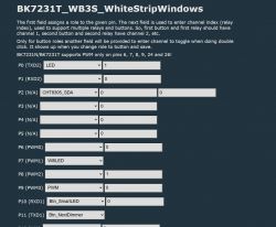
    Well, the LEDs are defined in the "Configure module" tab and there is a field to enter a linked channel number, see an example below:
    Configuration of BK7231T_WB3S module pins with assigned channels and roles for each pin.
    What do you want to do with that LED? Is your LED on P6?

    If you set a channel, let's say, channel 5 for P6, and set LED role for P6, then you will be able to control this LED manually via channel 5.

    If you want then to manually toggle channel 5 (the one that has linked LED now), you can write in script:
    
    toggleChannel 5
    

    or
    
    setChannel 5
    

    The following line will toggle channel 5 and all LEDs and RELs (and LED_n, and REL_n) on this channel will follow.

    Alternatively, you can set P6 (your LED) role to WIFILED_n, then it will automatically without channel and display your WiFi state.
    Helpful post? Buy me a coffee.
  • #18 20988984
    hezipereg
    Level 7  
    Yes the LED is on P6.
    OK now I understand how to set a channel. I managed as you showed me to add channel for the LED and called it light. Now I have a button in Home Assistant to toggle the switch LEDs. Setting P6 as Rel_n is the way the toggle button was added.
    I didn't understand what you said regarding
    Quote:
    Alternatively, you can set P6 (your LED) role to WIFILED_n, then it will automatically without channel and display your WiFi state.
    In that case, how will I be able to turn on/off the LEDs?
  • #19 20988997
    p.kaczmarek2
    Moderator Smart Home
    There are two ways to control LEDs.
    - first way is to assign a LED (or a LED_n, which is inversed LED) role and a channel, then LED will follow the channel and will be scriptable and controllable by user
    - the second way is to assign a WiFiLED role, which will make LED display the WiFi state (fast blinking when connecting, etc, etc, on when connected, etc)

    You can read more about IO roles here:
    https://github.com/openshwprojects/OpenBK7231T_App/blob/main/docs/ioRoles.md
    Table describing the states of LED WiFi and LED WiFi_n.

    hezipereg wrote:

    I didn't understand what you said regarding
    Quote:
    Alternatively, you can set P6 (your LED) role to WIFILED_n, then it will automatically without channel and display your WiFi state.
    In that case, how will I be able to turn on/off the LEDs?

    WIFI_LED is not controllable by user, it just displays the state of your WiFi connection. If you want to be able to manually control the LED, then choose LED (or LED_n) state.

    Some Tuya devices have two onboard LEDs and in their case users choose to configure first LED as WiFiLED_n to display WiFi state and to configure second LED as LED on the same channel which Relay is using to display the relay state.
    Helpful post? Buy me a coffee.
  • #20 20989113
    hezipereg
    Level 7  
    That worked (setting it as LED_n), assigning a channel and adding the channel to the autoexec.bat script.
    The perfect solution for me is to have both the wifi indication and to be able to control it.
    Quote:
    Some Tuya devices have two onboard LEDs and in their case users choose to configure first LED as WiFiLED_n to display WiFi state and to configure second LED as LED on the same channel which Relay is using to display the relay state.

    How do I know if this is the case here?

    Additionally, some of these switches have a slider to control open/close by percentage:
    App interface showing sliders with a hand icon
    Is it possible to do this logic?
  • #21 20989611
    p.kaczmarek2
    Moderator Smart Home
    hezipereg wrote:

    Quote:
    Some Tuya devices have two onboard LEDs and in their case users choose to configure first LED as WiFiLED_n to display WiFi state and to configure second LED as LED on the same channel which Relay is using to display the relay state.

    How do I know if this is the case here?

    Was there two LEDs blinking before you flashed device?
    When you open device case, are there multiple LEDs?
    When doing Tuya Config extraction:
    https://www.youtube.com/watch?v=WunlqIMAdgw&ab_channel=Elektrodacom
    are there multiple LEDs found?
    If you use GPIO Doctor from the Web App, are you able to find multiple GPIOs with LEDs?

    hezipereg wrote:

    Additionally, some of these switches have a slider to control open/close by percentage:
    App interface showing sliders with a hand icon
    Is it possible to do this logic?

    It's certainly possible to do that and I think I may have already seen as user-made script for that on our forum, but I am not sure where it was. This requires some changes to autoexec.bat. You need to have some basic programming knowledge for that. We may try to do something like that but I don't have shutters at home so you'll have to be the one testing.
    Helpful post? Buy me a coffee.
  • #22 20989757
    hezipereg
    Level 7  
    Quote:
    Was there two LEDs blinking before you flashed device?
    When you open device case, are there multiple LEDs?
    When doing Tuya Config extraction:
    https://www.youtube.com/watch?v=WunlqIMAdgw&ab_channel=Elektrodacom
    are there multiple LEDs found?
    If you use GPIO Doctor from the Web App, are you able to find multiple GPIOs with LEDs?

    I don't remember how many LEDs were blinking. I will try to do the Tuya configuration extraction later tonight and will update accordingly.

    Quote:
    It's certainly possible to do that and I think I may have already seen as user-made script for that on our forum, but I am not sure where it was. This requires some changes to autoexec.bat. You need to have some basic programming knowledge for that. We may try to do something like that but I don't have shutters at home so you'll have to be the one testing.

    I have programming skills. I am a programmer mainly for embedded systems using C, python, etc.. I am up for the challenge. No problem, I will debug it myself. Thanks!
  • #23 20989828
    p.kaczmarek2
    Moderator Smart Home
    Ok, so if you want to have a slider, let's start with determining which variable we need to change.

    If I understand correctly, you want to make this delay:
    
    resetCloseAfterDelay:
    // wait $CH4 seconds
    delay_s $CH4
    // stop opening
    SetChannel 1 0
    // done
    return
    

    configurable with a slider?

    Or, actually, it doesn't look like it. It seems that we need to introduce a separate variable to store how much the shutter is open.... because channel 4 is a time required to fully open or close the shutter.

    So maybe we can introduce a separate channel, let's say with a type of Slider (that has range 0-100) and then normalize it to 0-1 range and multiply the open/close time by that? Of course, that's not the full logic.
    Helpful post? Buy me a coffee.
  • #24 20990076
    hezipereg
    Level 7  
    I know the logic, I don't know how to implement it in OpenBeken.
    The logic (pseudo code) should be as follows:
    1. define an input number which holds the time it takes for the shutter to open/close - `fully_open_close_duration`.
    2. define an input number which holds the number of seconds left for the shutter to open/close - ` open_duration_left`.
    3. define a shutter position (slider) which we could calibrate manually for example to fully open or fully close somehow. This calibration should also change ` open_duration_left`. For example if we calibrate to fully close then ` open_duration_left` = `fully_open_close_duration`
    4. once an open/close operation occurs, count the number of seconds. This should take into account if stop button was pressed - `last_operation_duration`
    5. If the operation was open then ` open_duration_left` -= `last_operation_duration` else if close ` open_duration_left` += `last_operation_duration`.
    6. set the shutter position according to the following : ((` open_duration_left` / `fully_open_close_duration`) * 100).

    Now if you use the slider to open/close:
    1. Get slider position change. We can save `previous_shutter_position` and `current_shutter_position`.
    2. Calculate the number of seconds the shutter should be open close by the change (`previous_shutter_position` - `current_shutter_position`). For example if the change is from 60% open to 70% open then the shutter should be opened for 10% * `fully_open_close_duration` seconds.
    3. change ` open_duration_left` accordingly.

    Something like that.
  • #25 20990079
    p.kaczmarek2
    Moderator Smart Home
    Before we consider the scripting approach, maybe it would be worth looking into the C code itself?

    Here are our drivers:
    https://github.com/openshwprojects/OpenBK7231T_App/tree/main/src/driver
    Here is a sample driver:
    https://github.com/openshwprojects/OpenBK7231T_App/blob/main/src/driver/drv_chargingLimit.c
    Here is another one:
    https://github.com/openshwprojects/OpenBK7231T_App/blob/main/src/driver/drv_pwmToggler.c

    Maybe it would be easier to just make a dedicated driver for shutters? I can help, it's just that I don't have shutters. Do you know C?
    Helpful post? Buy me a coffee.
  • #26 20990145
    hezipereg
    Level 7  
    Sure I know C.
    Let's try to do the driver.
  • #27 20990148
    p.kaczmarek2
    Moderator Smart Home
    Ok, so first you need to add an entry to drivers table here:
    https://github.com/openshwprojects/OpenBK7231T_App/blob/main/src/driver/drv_main.c
    Here is a structure of a driver:
    Code: C / C++
    Log in, to see the code

    Name your driver "shutters" and then you can create a separate file called drv_shutters.c and add the stub functions there.

    The functions itself should be self-explanatory but when in doubt you can just peek into other drivers, for example here is a bridge relay driver:
    https://github.com/openshwprojects/OpenBK7231T_App/blob/main/src/driver/drv_bridge_driver.c

    Do you know Git? If you open that in a draft pull request, I can monitor your activity and give more detailed hints.
    Helpful post? Buy me a coffee.
  • #28 20990212
    hezipereg
    Level 7  
    I know GIT. I work with GitLab which is quite similar to GitHub.
    In order to open a draft pull request, I need to first open a new branch right or an issue and then pull request from that issue?

    Added after 1 [hours] 4 [minutes]:

    In the meantime I've added the following
    drv_main.c:
    Code: C / C++
    Log in, to see the code


    drv_shutter.c
    Code: C / C++
    Log in, to see the code


    The VS project does not compile?
  • #29 20990344
    p.kaczmarek2
    Moderator Smart Home
    You need to create a branch. Issues are irrevelant for creating PR.

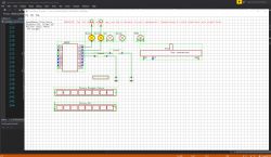
    The VS project is for Windows Simulator, which I use to quickly debug things. It allows you to run virtual OBK device on Windows:
    OpenBeken simulator diagram with electronic circuit on a grid.

    To compile BK7231 build, you need to either:
    1. use online github builds:
    https://www.elektroda.com/rtvforum/topic4033833.html
    2. checkout SDK, either T or N:
    https://github.com/openshwprojects/OpenBK7231T
    https://github.com/openshwprojects/OpenBK7231N
    checkout app to the SDK:
    https://github.com/openshwprojects/OpenBK7231T_App
    so your path is:
    C:/Anything/GIT/OpenBK7231T/apps/OpenBK7231T_App
    run build in cygwin
    Screenshot of script compilation in Cygwin terminal for the BK7231T platform.
    Helpful post? Buy me a coffee.
  • #30 20990439
    hezipereg
    Level 7  
    Quote:
    You need to create a branch. Issues are irrevelant for creating PR.

    I don't have the open branch button available.

    Quote:
    run build in cygwin

    I tried to build using wsl. I get: ./b.sh: 1: ./build_app.sh: not found

    I tried calling ./build_app.sh apps/OpenBK7231T_App OpenBK7231T_App 1.0.0 and got ./build_app.sh: bad interpreter: /bin/sh^M: no such file or directory

Topic summary

The discussion centers on the BK7231N-based LoraTap SC400W-EU switch board, focusing on desoldering challenges, flashing procedures, and firmware customization using OpenBeken. Initial difficulties in desoldering the switch pins led to partial soldering of RX, TX, VCC, and GND for flashing via shorting GND to CEN. Users shared detailed GPIO pin mappings for LEDs, buttons, and relays, clarifying LED roles such as LED, LED_n (inverted), and WifiLED_n, with hardware limitations restricting color control to on/off states. Configuration adjustments via the autoexec.bat script enabled control of LED states and introduced a runtime parameter for shutter open/close duration, which was integrated with Home Assistant through MQTT and input_number entities. Advanced users discussed developing a dedicated shutter driver in C within the OpenBK7231T_App framework, including driver structure, function callbacks, and build environment setup using Cygwin or WSL. Troubleshooting build issues and GitHub workflow for pull requests were addressed. The conversation also covered TuyaMCU device considerations, flashing tools, and extracting Tuya configurations. Finally, a user shared a custom blind driver script for the LoraTap SC400W-EU, emphasizing unique pin assignments and MQTT integration for Home Assistant control, highlighting the variability of hardware revisions.
Summary generated by the language model.
ADVERTISEMENT