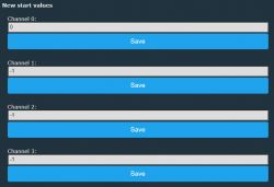
Hi,
Recently I have bought this socket https://www.aliexpress.com/item/1005005583141499.html?spm=a2g0o.order_list.order_list_main.88.26e8180268ZrMC which is similar to https://www.elektroda.com/rtvforum/topic3892473.html#20014441 with some differences. Pinout is slightly different and has 3 relays.
Device configuration, as extracted from Tuya:
- Relay (channel 3) on P7
- Pair/Toggle All Button on P10
- WiFi LED on P8
- Relay (channel 2) on P24
- Relay (channel 1) on P26
Device seems to be using CB2S module, which is using BK7231N.
And the Tuya section starts, as usual, at 2023424
This is json code:
OpenBeken template:
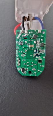
And some pictures

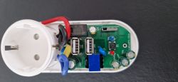
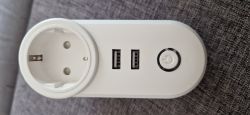
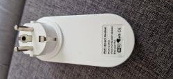

Added after 18 [minutes]:
Because I am new with openbeken I'am seeking some help.
I don't know if I'm doing something wrong:
1. It appears that LED light shows as Button. If I toggle the blue light turns on and off, without any relay changes
2. Btn Toggle All is missing in web gui
3. Is it possible to include Btn toggle all to Home Assistant using mqtt?
4. How can I configure the relay's last state? After wifi reconnects, Relay 0 is switched on, but USB relays are off.
Thank you
Recently I have bought this socket https://www.aliexpress.com/item/1005005583141499.html?spm=a2g0o.order_list.order_list_main.88.26e8180268ZrMC which is similar to https://www.elektroda.com/rtvforum/topic3892473.html#20014441 with some differences. Pinout is slightly different and has 3 relays.
Device configuration, as extracted from Tuya:
- Relay (channel 3) on P7
- Pair/Toggle All Button on P10
- WiFi LED on P8
- Relay (channel 2) on P24
- Relay (channel 1) on P26
Device seems to be using CB2S module, which is using BK7231N.
And the Tuya section starts, as usual, at 2023424
This is json code:
{
	"rl1_lv":"1",
	"bt_type":"0",
	"rl3_pin":"7",
	"rl3_lv":"1",
	"net_trig":"2",
	"jv":"1.0.0",
	"netled1_lv":"0",
	"netled_reuse":"0",
	"total_bt_pin":"10",
	"nety_led":"1",
	"total_stat":"2",
	"reset_t":"5",
	"netled1_pin":"8",
	"rl2_lv":"1",
	"module":"CB2S",
	"ch_cddpid1":"9",
	"rl2_pin":"24",
	"ch_cddpid2":"10",
	"ch_cddpid3":"11",
	"total_bt_lv":"0",
	"ch_num":"3",
	"rl1_pin":"26",
	"ch_dpid3":"3",
	"netn_led":"0",
	"ch_dpid1":"1",
	"ch_dpid2":"2",
	"crc":"59",
	"}4 &Agw_di{abi":"0",
	"id":"null",
	"swv":"1.1.15",
	"bv":"40.00",
	"pv":"2.2",
	"lpv":"3.4",
	"pk":"keyjup78v54myhan",
	"firmk":"keyjup78v54myhan",
	"cadv":"1.0.5",
	"cdv":"1.0.0",
	"dev_swv":"1.1.15",
	"s_id":"null",
	"dtp":"0",
	"sync":"0",
	"attr_num":"1",
	"mst_tp_0":"9",
	"mst_ver_0":"1.1.15",
	"mst_md5_0":"null",
	"mst_tp_1":"0",
	"mst_ver_1":"null",
	"mst_md5_1":"null",
	"mst_tp_2":"0",
	"mst_ver_2":"null",
	"mst_md5_2":"null",
	"mst_tp_3":"0",
	"mst_ver_3":"null",
	"mst_md5_3":"null }0Atls_ca_cnt0 .MAgw_wsm{nc_tp",
	"ssid":"null",
	"passwd":"null",
	"md":"0",
	"random":"0",
	"wfb64":"1",
	"stat":"0",
	"token":"null",
	"region":"null",
	"reg_key":"null",
	"dns_prio":"0 }{uuid",
	"psk_key":"tIifVCRMFEUE4LGN5crm9kUb2D248mljvhK09",
	"auth_key":"TaMAFMiYg6zqkGivWBaiI85WxIH9GeQx",
	"ap_ssid":"SmartLife",
	"ap_passwd":"null",
	"country_code":"null",
	"bt_mac":"null",
	"bt_hid":"null",
	"prod_test":"false",
	"fac_pin":"xjibhmsjf3hqrbcc }3Awf_start_mdll",
	"lckey":"null",
	"h_url":"null",
	"h_ip":"null",
	"hs_url":"null",
	"hs_ip":"null",
	"hs_psk":"null",
	"hs_psk_ip":"null",
	"mqs_url":"null",
	"mqs_ip":"null",
	"mq_url":"null",
	"mq_ip":"null",
	"ai_sp":"null",
	"ai_sp_ip":"null",
	"mq_psk":"null",
	"mq_psk_ip":"null",
	"lp_url":"null",
	"lp_ip":"null",
	"time_z":"null",
	"s_time_z":"null",
	"wx_app_id":"null",
	"wx_uuid":"null",
	"dy_tls_m":"0",
	"cloud_cap":"0",
	"psk21_key":"null }ok5A0000038zlb[{type",
	"mode":"rw",
	"property":"{type",
	"{type":"obj",
	"max":"86400",
	"scale":"0",
	"step":"1",
	"type":"value}",
	"maxlen":"255}",
	"index":"0}@Amf_test_closetrueDNMAgw_ai{key",
	"m3nc_tp":"0"
}
OpenBeken template:
{
  "vendor": "Tuya",
  "bDetailed": "0",
  "name": "Full Device Name Here",
  "model": "enter short model name here",
  "chip": "BK7231N",
  "board": "TODO",
  "flags": "0",
  "keywords": [
    "TODO",
    "TODO",
    "TODO"
  ],
  "pins": {
    "7": "Rel;3",
    "8": "LED;0",
    "10": "Btn_Tgl_All;0",
    "24": "Rel;2",
    "26": "Rel;1"
  },
  "command": "",
  "image": "https://obrazki.elektroda.pl/YOUR_IMAGE.jpg",
  "wiki": "https://www.elektroda.com/rtvforum/topic_YOUR_TOPIC.html"
}
And some pictures


Added after 18 [minutes]:
Because I am new with openbeken I'am seeking some help.
I don't know if I'm doing something wrong:
1. It appears that LED light shows as Button. If I toggle the blue light turns on and off, without any relay changes
2. Btn Toggle All is missing in web gui
3. Is it possible to include Btn toggle all to Home Assistant using mqtt?
4. How can I configure the relay's last state? After wifi reconnects, Relay 0 is switched on, but USB relays are off.
Thank you
Cool? Ranking DIY


