logo elektroda
logo elektroda
X
logo elektroda

[T34/BL0937] Teardown Generic Wifi Smart Plug with Energy Measurement

Raufaser 17451 132
ADVERTISEMENT
  • #91 21366840
    rufus4
    Level 10  
    1. CRC error --> no saved file
    2. The temperature of the processor stays the same. Hot! /-60°C
  • ADVERTISEMENT
  • #92 21368805
    rufus4
    Level 10  
    I did some research about my observation of the internal temperature rising.

    With OpenBK7231N_1.17.678 there was a change called "calibrate temperatures reading".
    https://github.com/openshwprojects/OpenBK7231...mmit/9becf09ae8b8749c62fc13e03a6a2431679eef7d

    Since then the internal temperature is much higher. When I did realize this for the first time two days ago, I was playing around with `PowerSave` and it didn't make any differences on temperatures. So I thought it's not working anymore.
    But now I was testing `PowerSave` with 1.17.656 and I have seen that it makes no differences at internal temperatures as well.
    So... was `PowerSave` actually working anytime on this specific device? Maybe on an older FW or maybe never ever?
  • #93 21370940
    wrona80
    Level 14  
    @no_cloud Maybe try to put power cables closer to T34
    Close-up of a circuit board with labeled pins GND, RXD, TXD, and 3V3 on the T34 chip.
  • #94 21371180
    tun0
    Level 6  
    fatalbullethit wrote:
    p.kaczmarek2 wrote:
    Do Tuya Config extraction, set BL0937 pins and it will work well.

    Thanks for the quick reply, unfortunately I get the following error: "Failed to extract keys"
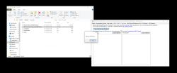
    Screenshot of a software tool for extracting keys from firmware files.
    I tried both, the tuya config and a complete dump. Any ideas?

    Edit:
    I did flash ESPHome to it and reverted to OpenBeken, not sure if this might cause issues.
    I'll flash OpenBeken to another one I've laying around and will extract the config again and report back.


    Could you share your ESPHome configuration?
  • ADVERTISEMENT
  • #95 21372126
    tun0
    Level 6  
    I just can't seem to get around the "getting bus failed", also with this type of socket. The USB UART dongle can power a ESP12 or ESP8266 board just fine, so I doubt it's a power issue.

    The sockets that I have look identical to this:

    kubanekjiri wrote:
    I tried it with BL0492 connected and it works!!!
    Close-up of a circuit board with connected wires.


    Also using the same pins to solder to.

    The only thing that does "feel" like a power issue, is the fact that every now and then the usb device reconnects when power cycling the T34.
  • ADVERTISEMENT
  • #96 21372129
    divadiow
    Level 34  
    That sounds like the USB-TTL can't provide enough current. I wasted hours trying to flash in the early days without external 3.3v :)
  • #97 21372447
    tun0
    Level 6  
    divadiow wrote:
    That sounds like the USB-TTL can't provide enough current. I wasted hours trying to flash in the early days without external 3.3v :)

    I kinda agree. But when connected, the socket's blue LED does start blinking. And I can also power ESP8266 boards with it for example. But, guess I'll be ordering yet another USB-TTL just to be sure. Now if only they'd provide actual numbers regarding the power capabilities of the LDO dropdown, etc.
  • Helpful post
    #98 21373301
    vitya123
    Level 6  
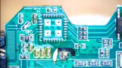
    A bit late for the party, but I thought I'd chip in with a method of programming these "test pointless" sockets. I saw that it gave grief to some people here that the Tx pin is not easily accessible. Some people resorted to removing the chip altogether and programming it like that. I also did that the first time. It worked, but it is certainly not for everybody :)
    However, once I removed the chip I inspected the pads underneath and concluded that the Rx and Tx pins are not connected anywhere else:

    Close-up of a printed circuit board with various electronic components and visible pins.
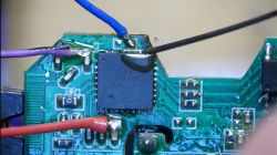
    This lead to the idea to just leave the chip in place, solder the 3.3V, GND and Tx pins as shown in earlier posts. The Rx pin (#25) is the tricky one. The easiest solution I could come up with is to use a needle and hold it against the pin by hand during the reading/flashing. It is very easy, no micro soldering is needed, just a steady hand :)
    This is how it looks with the 3 wires soldered and the needle held against Rx:

    Close-up of a circuit board with soldered wires and a needle positioned on a pin.
    (I would like to apologize using a purple wire for GND - I just didn't have a black one at hand...) The red wire is 3.3V (external supply - NOT provided by the USB-UART adapter), the blue wire is Tx.

    I found this method the fastest, easiest and the one that requires the least specialist tools/skills.
    Here is a short video showing the method:


    I hope it will help some...
  • #99 21375288
    viktorpot
    Level 2  
    donotos wrote:

    Hey.
    I just finished flashing my own so thanks for the help provided here.
    I wasn't able to flash by powering the T34 with the UART. Every time I disconnected 3v3 it disconnected from USB and killed the flasher app so I had to use an external PSU.

    BTW: inverting polarity did not kill the T34!

    I had some troubles wiring the chip so here is a small schematic:
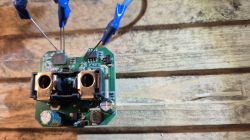

    Diagram of a connection setup between T34, BL0937, and FT232RL with 3.3V power supply.


    Thank you for this simple schematic! It helped me a lot to easily flash several of these devices quickly without any soldering using these DIY pins that I have seen in another thread.

    Close-up of a circuit board with three connected wires.

    Looking at your schematic I guess I should use BL0937 driver? I have followed all advice in this thread I've just realized that I am using 2 drivers (PIN assigned as well as startup command for BL0942). I guess I should remove the BL0942 driver from my startup command. Will play around with that later.
  • #100 21375310
    vitya123
    Level 6  
    @viktorpot I'd say, ignore any schematics :) and go with the chip you have on your board - experiments beat theory :))) If I'm not mistaken it's the 8 pin SOIC chip in the top right corner of your pic. If you can read what's on it, then go with that driver. If you can't read it, then you can start experimenting.
  • #101 21375327
    viktorpot
    Level 2  
    >>21375310

    Yeah right, it reads 0937 so I removed the BL0943 from startup and all seem fine now.
    I am new to this with only little ESP32 experience so it takes time to understand what I am doing and what the right settings are.
  • #102 21379273
    no_cloud
    Level 6  
    >>21364027 ok I try your method and I come back for results.
    Thank you for your help.
  • #103 21380665
    camillelieveux
    Level 2  
    Hi and happy new year,

    I am completely new with the IoT devices. I bought the same smart plug as the 1st message of this topic (T34 with BL0937).
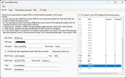
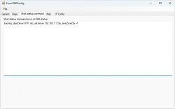
    I was able to flash the OpenBK7231N_QIO_1.17.822.bin firmware. The problem is that I don’t see any Access Point.
    Same result when I write the following OBK config:
    Screenshot of FormOBKConfig application showing WiFi and GPIO settings.
    Screenshot of FormOBKConfig software showing the startup command tab with a command entered.

    I attach the log file after flashing firmware: Flash2 fir...figOBK.txt Download (18.51 kB)

    Does anyone know what I’m missing or doing wrong?
    Thanks for your help and amazing work
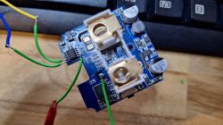
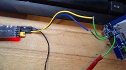
  • #104 21380873
    p.kaczmarek2
    Moderator Smart Home
    If you enter your WiFi and SSID data, as shown on the screenshot, the access point will not show up. Instead, OBK will try to connect your WiFi directly.

    If you want to run in access point mode, either make WiFi ssid/password fields blank, or do quick 5 power off and on cycles to run it as "safe mode ap".
    Helpful post? Buy me a coffee.
  • #105 21381561
    camillelieveux
    Level 2  
    Hi,
    Thank you very much for your help. Everything is OK
    I have another noob's question: the relay entity (not sure about vocabulary) is called "0". Is it possible to rename it in a parameter or config file?
    see the screenshot:
    Screenshot of a device management application's status section, highlighting a relay entity named 0.

    Thanks for your help
  • #106 21384105
    Tummi
    Level 13  
    >>21373301 Thank you, it helped a lot! ;) Strange behavior observed - flashing went smoothly after power was disconnected (red cable in your screenshot).
  • #107 21388345
    giacomo0217
    Level 2  
    Hi guys!
    I'm having some issues with this T34 smartplug.
    I've opened the case, soldered power and serial, flashed the OpenBK7231N_QIO_1.18.18 image with the BK7231 Easy UART Flasher but after the flash the smart plug is not creating the setup wifi network; I even tried flashing the config to connect to my wifi but nothing.
    The main led remains blue (with low brightness) and static.
    As a troubleshooting step, I even tried to erase the RF partition but still nothing, no wifi network.

    Am I doing something wrong? Am I missing something?
    Thanks!
  • #108 21388359
    p.kaczmarek2
    Moderator Smart Home
    How do you power it? It's a known issue that some WiFi chips won't work well if you power them directly from USB to UART converter. You need more current.
    Helpful post? Buy me a coffee.
  • #109 21388368
    giacomo0217
    Level 2  
    @p.kaczmarek2 >>21388359 >>21388359
    I thought the same as you, but it's doing the same thing with the power of an Arduino UNO and with the power of its built-in power supply.

    Added after 2 [minutes]:

    >>21388368
    PCB held by a service holder with connected power supply.
    Ignore the disconnected RX cable, this is with Arduino power
  • #110 21388398
    p.kaczmarek2
    Moderator Smart Home
    Maybe taking UTX2 (UART 2 TX, TXD2) log could help us to see what's going on, whether device boots or not, etc.
    Helpful post? Buy me a coffee.
  • #111 21394276
    mchipelo93
    Level 2  
    I'm going to make probably a silly question but...

    Circuit board with clamps for connecting a Schuko plug.

    What is the name of these terminals for the schuko plug? I've searched everywhere and I can't find it...
  • #112 21394453
    tun0
    Level 6  
    tun0 wrote:
    divadiow wrote:
    That sounds like the USB-TTL can't provide enough current. I wasted hours trying to flash in the early days without external 3.3v :)


    I kinda agree. But when connected, the socket's blue LED does start blinking. And I can also power ESP8266 boards with it for example. But, guess I'll be ordering yet another USB-TTL just to be sure. Now if only they'd provide actual numbers regarding the power capabilities of the LDO dropdown, etc.


    As it turned out, it was a power issue after all. Even though it has LDO regulator, it apparently wasn't providing enough power. Adding an external power supply did seem to do the trick. That is, after dozens and dozens of tries. Tons of attempts stalled either nearly the beginning of the dump process or roughly halfway. No idea what eventually "did the trick" to make it actually work. Too bad I was only able to convert 1 out of a set of 5 so far. As I managed to have the magic smoke leave the AMS117 of the power supply used. New one is on the slow boat from China (it's one of the power supplies you can plug directly into a breadboard).
  • #113 21403006
    divadiow
    Level 34  
    now I've been cursed with one of these while hoping for a Realtek module. oh well.

    Interior of an electronic device with a visible circuit board and components.

    Added after 1 [minutes]:

    mchipelo93 wrote:
    What is the name of these terminals for the schuko plug? I've searched everywhere and I can't find it...

    these?

    Close-up of a circuit board with two sockets marked in red.
  • #114 21403512
    p.kaczmarek2
    Moderator Smart Home
    Those plugs would be better with BL0942, in such case we would have RX/TX connected to BL0942 pins....
    Helpful post? Buy me a coffee.
  • ADVERTISEMENT
  • #115 21409547
    auntlydia
    Level 10  
    Thanks for this teardown and settings! There is another revision of this device which has BL0942 and I created a topic for it
    --> https://www.elektroda.com/rtvforum/topic4099021.html

    The settings are slightly different and the chip is smaller and is a different socket without legs.

    (I think it's the same one here:
    kubanekjiri wrote:
    I tried it with BL0492 connected and it works!!!
    Close-up of a circuit board with connected wires.
    )
  • #116 21420827
    dixy1
    Level 2  
    [solved] Solution: I use the wrong place for the GND there. If I connect the Power and the GND directly at the pins from BL0942 the programming starts. For this solution have a look at the last 2 new pictures

    Addendum: I ordered more switch sockets from the shop mentioned below. For some of the switch sockets, the button was not working after flashing... before flashing, the button worked perfectly. At first I was confused because I always used the same file to flash. The solution: individual flags were set, not just flag 10. Flag 41 - [BTN] Ignore all button events (aka child lock) was set, among other things. This meant that the switch was not working! So after flashing, check all flags in the menu item "Configure General/Flags". :-)

    Hello,
    I have a problem to flash my Tuya 20A Smart plug from Aoyan AE Store (Aliexpress). Using a CH340 USB to TTL Programmer and the BK7231Flasher-V5 program.

    If I start it it looks like this:

    Backup name is set to T.
    Starting read backup and flash new!
    Now is: Samstag, 1. Februar 2025 23:28:51.
    Flasher mode: BK7231N
    Going to open port: COM5.
    Serial port open!
    Getting bus... (now, please do reboot by CEN or by power off/on)
    Getting bus failed, will try again - 0/100!

    ...

    For me it’s not problematic to make the 4 connections to the board and put some external 3.3V to the device. I also tried the BK7231Flasher-V4 version and another CH340 USB to TTL Programmer. But still "Getting bus failed" message. The COM port is correct, the RX-TX and TX-RX connection to the BL0942 is ok, the ground from the Programmer and the external 3.3V is there and I also switched the 3.3V off for a moment after starting the process. I will attach some pictures. What’s going wrong in this case?


    Greetings
    dixy1
    wrong GND connection at the socket, don`t do it like that!
    Connected circuit board with incorrect ground connection.
    USB to TTL connection using wires to a circuit board.
    Connection wires attached to an electronic board on a desk.
    USB to TTL adapter with connected wires on a wooden surface.

    Solution: (connect it directly at BL0942
    Electronic circuit board with colored wires connected to a USB to TTL adapter.
    Electronic module with connected wires
  • #117 21420891
    max4elektroda
    Level 20  
    The usual advices:
    Use external 3.3V power
    Keep cables as short as possible
    Re-check the connections
    Use a lower and maybe even higher UART speed.

    I can add, just to be sure, does your device use a BL0942? I can't read the chip version on the picture. Just in case you have a slightly different version where the power metering chip doesn't use RX/TX as expected.

    Added after 23 [minutes]:

    As I don't own such a device with BL0942 it's just an educated guess: to have a first check of your cables and power you should just power the device with a serial monitor open. You should be able to see the communication between MCU and power metering chip with speed 4800 if I got it right.
  • #118 21422095
    p.kaczmarek2
    Moderator Smart Home
    BL0937 has 8 pins and BL0942 has usually 10, so I would still gues he has BL0942.
    BL0937 integrated circuit with eight pins
    Helpful post? Buy me a coffee.
  • #120 21439982
    EchoSin
    Level 9  
    Hi, thanks for your posts enabling me to upload OpenBeken to my socket. I thought I'd describe the whole process.

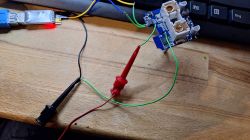
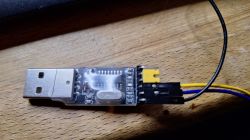
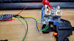
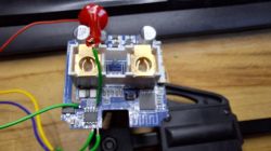
    I opened the case by squeezing both sides diagonally in a vise until I heard a quiet snap. I covered the case with a paper towel. Then all I had to do was slide the top out, unscrew the two screws and pull the board out. This was done without soldering to the board. I made myself a jig from a wooden block in which I drilled two holes for the socket pins. To the block I screwed copper electrical wires terminating in pins fixed with clamps from the electrical cube. (I cut the heads off the pins first. Sorry...) To the block I also screwed in a regulated power supply module (with which I fed 3.3 V), a voltmeter and a socket to connect the power supply (5 V from an old router). This way I had everything together, easy to carry and without worrying that I would pull a cable and something would get disconnected. I made the connections as my colleague donotos https://www.elektroda.pl/rtvforum/topic4042412.html#21054371, even with the same FTDI232RL programmer. The important thing is not to make a mistake and connect the RX to TX correctly (and not as I did mistakenly RX to RX and TX to TX). You need to install a driver for this programmer on Windows 10. I downloaded it from `ftdichip.com/drivers` (link here) and installed it by running the .exe file. In BK7231GUIFlashTool-v5 in the Select UART port: field COM3 was automatically selected, in the `Select chip type` field I selected BK7231N and pressed `Download latest from Web`. The version that downloaded was OpenBK7231N_QIO_1.18.37. I set the baud rate to 921600 and set the same value in the windows (Windows 10) Device Manager to the COM3 port (COM and LPT Ports > USB Serial Port (COM3) > right click > Properties > Port Settings > Number of bits per second). I then clicked the Do backup and flash new button. The console displayed that it was trying to connect to the canbus and was making further attempts. At this point I disconnected the external 3.3V power supply and reconnected. With that, the backup and flashing process started and completed successfully. I removed the board from the instrument and inserted it into the case, which I temporarily sealed with insulating tape. I inserted the smart socket into a regular socket. Now on the laptop, I searched for a wireless network that had something resembling OpenBeken in its name (I no longer remember the exact name) and connected to it. In the Network and Internet Settings I found the local IP address of my socket: 192.168.4.1, which I then accessed in my web browser. On the page that appeared at this address, I selected `Launch Web Application` and went to the `Import` tab. In the `Enter template here` field, I pasted the configuration copied from the `openbekeniot.github.io/webapp/devicesList.html` page for the (QNCX) Generic Smart Plug with Energy Measurement (T34) device (LSPA9 clone). I removed the socket from the socket and reinserted it. I went into 192.168.4.1 again, this time into the Config section, where I set my home network name and password for the WIFI uuid. I connected the laptop again to my home router. I went to 192.168.1.1, found my socket there and checked what IP address it had. I went to the IP address of my socket on my home network and was already able to use it. I still had to calibrate the electricity measurement in the Web Application.

    Observations:
    1. chip temperature: 55.9 °C (with relay off)
    2. the socket button does not work. I can only switch the socket on and off via WiFi.

    I am wondering what I can do to make this button work.

    Electronic circuit board with attached wires and components on a wooden block. .
    Simplified electronic device with colorful wires on a wooden base.

Topic summary

The discussion revolves around the teardown and modification of a generic WiFi smart plug, specifically the T34 model, which features energy measurement capabilities. Users share their experiences with soldering connections for UART flashing, troubleshooting issues with the T34 chip, and the challenges faced during the process. Key points include the identification of the chip as BK7231N, the use of OpenBeken firmware, and the importance of proper pin connections for successful flashing. Users also discuss power consumption measurements and the implications of power-saving modes. The conversation highlights various techniques for soldering and the significance of component values, such as capacitors, in the device's functionality.
Summary generated by the language model.
ADVERTISEMENT