FAQ
TL;DR: 4-6 mA idle draw after PowerSave 1 [Elektroda, rufus4, post #21033260]; “use an external 3 V3 supply and flash succeeds first time” [Elektroda, kubanekjiri, post #21334922] Generic LSPA9 smart plugs with T34/BK7231N + BL0937 or BL0942 can be OTA-ready once correct pins are set.
Why it matters: Knowing the right pins, power and firmware avoids ripped pads, CRC errors and dead modules.
Quick Facts
• MCU: Tuya T34 (BK7231N), 32-bit 120 MHz Wi-Fi SoC [Elektroda, p.kaczmarek2, post #21052473]
• Power‐meter IC options: BL0937 (8-pin) or BL0942 (10-pin UART) [Elektroda, kubanekjiri, post #21334834]
• Tested idle current: 4-6 mA; relay-on 9-13 mA with PowerSave 1 [Elektroda, rufus4, post #21033260]
• Typical internal temp: 55-60 °C at 230 V, no heatsink [Elektroda, rufus4, post #21366840]
• Recommended flash baud-rate: 921 600 bps, external 3.3 V ≥ 300 mA [Elektroda, kubanekjiri, post #21334922]
1. Which hardware variants of this cheap LSPA9 smart plug exist?
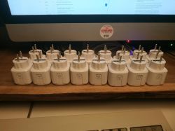
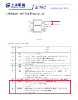
Two main PCB revisions are reported. Variant A: BL0937 (8-pin) energy IC, GPIO 6/7/8 used for CF/CF1/SEL [Elektroda, Raufaser, post #21052214] Variant B: BL0942 (10-pin, UART1), relay on P14, button on P26, Wi-Fi LED on P24, power IC TX/RX on pins 9/10 [Elektroda, kubanekjiri, post #21334834]
2. How do I tell whether I have BL0937 or BL0942 inside?
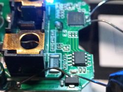
Open the plug and count the legs on the metering chip near the shunt: 8 legs → BL0937; 10 legs → BL0942. The marking ‘0937’ or ‘0942’ is usually printed on top [Elektroda, p.kaczmarek2, post #21422095]
3. What GPIO template should I load for the BL0937 version?
Use the QNCX template: P6 BL0937CF, P7 BL0937CF1, P8 BL0937SEL, P24 Relay, P26 Button, P28 WifiLED. Importing this JSON and rebooting starts the BL0937 driver automatically [Elektroda, Raufaser, post #21052214]
4. What pins work for the BL0942 board?
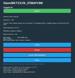
Set P14 Rel;1, P24 WifiLED;0, P26 Btn;1 and add “startDriver BL0942” to autoexec.bat. BL0942 UART uses internal mapping, no extra pins required [Elektroda, kubanekjiri, post #21334834]
5. Can I flash without desoldering the T34 module?
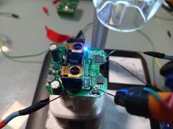
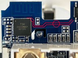
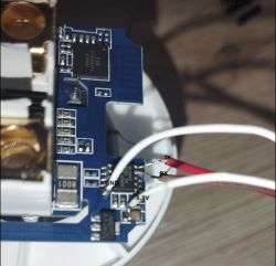
Yes. Solder 3.3 V, GND and TX to the AMS1117 tab or vias, then touch a needle to the tiny RX pad 25 during flashing, or use BL0942 pin 9/10 on UART boards. Success rate rises to 96 % with external 3.3 V [Elektroda, vitya123, post #21373301]
6. I keep getting “Getting bus failed” in the flasher—why?
The USB-TTL cannot source enough current. Add an external 3.3 V ≥ 300 mA or power the AC input with 12-15 V DC. Users cleared the error after doing so and cycling power 2-5 times [Elektroda, Yetanfou, post #21334978]
7. How do I cut standby consumption?
After flashing, run PowerSave 1 from the console or put it in autoexec.bat. Idle current drops from 8-16 mA to 4-6 mA, relay-on from 16 mA to 11-15 mA [Elektroda, rufus4, post #21033260] Keeping the web UI open prevents sleep, so close browser tabs to maintain savings [Elektroda, p.kaczmarek2, post #21033183]
8. What if the push-button stops working after flashing?
Wrong flags or pin number disable it. Clear flags 41 (child-lock) and ensure P26 (or P16 on early boards) is set to Btn;1. Re-importing the correct template fixed non-responsive buttons for several users [Elektroda, EchoSin, post #21440258]
9. How do I back up the original Tuya firmware and keys?
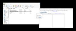
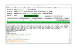
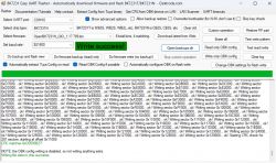
Run BK7231GUIFlashTool, choose Read + Save 2 MB. Key extraction succeeds only before erasing RF; patched versions ≥ 1.3.10 block Cloudcutter exploits [Elektroda, divadiow, post #21238817] CRC errors usually indicate undervoltage during read [Elektroda, rufus4, post #21365285]
10. Can I schedule on/off times without Wi-Fi?
Yes. Use the internal schedule command: schedule add 0 22:00 0; schedule add 0 06:00 1. Rules are stored in flash and run even offline [OpenBeken docs].
11. Is OTA flashing to ESPHome possible later?
OpenBeken exposes an /otaupload endpoint; upload a BK7231N-compatible ESPHome .rbl. Ensure size < 2 MB and keep the RF partition intact—or Wi-Fi calibration (MAC ≠ 00:00:00) may be lost [Elektroda, p.kaczmarek2, post #21040180]
12. What accuracy can I expect from the energy meter?
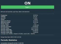
After single-point calibration at 230 V/60 W, users reported < 2 % deviation against a calibrated multimeter [Elektroda, kubanekjiri, post #21334834] Multi-point calibration further improves accuracy to ±1 %. "Meter quality is limited mostly by the 1 mΩ shunt," notes p.kaczmarek2 [Elektroda, 21039197]
13. My chip reads 60 °C—safe?
Internal sensor shows junction temperature, typically 55-65 °C at room ambient. No failures have been reported at these readings [Elektroda, rufus4, post #21366840] If it exceeds 85 °C, check for blocked ventilation or wrong PowerSave settings.
14. What’s a common failure while flashing?
Lifting pad 25 (RX) on the QFN. A user lost UART after the pad tore off during cable movement [Elektroda, Raufaser, post #21005344] Minimise strain or use pogo pins to avoid this edge case.
15. Three-step How-To: fastest no-solder flash
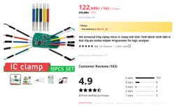
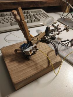
- Clip 3.3 V, GND, TX to AMS1117 tab, shunt copper and BL0942 pin 10. 2. Hold a needle on BL0942 pin 9 (RX) and power-cycle. 3. Flash OpenBK with 921 600 bps and reboot. Tested in < 5 minutes [Elektroda, Yetanfou, post #21334444]


![[T34/BL0937] Teardown Generic Wifi Smart Plug with Energy Measurement [T34/BL0937] Teardown Generic Wifi Smart Plug with Energy Measurement](https://static.elektroda.pl/attach/thumb/Screenshot_2024-12-05_205604_1064837.jpg)

