logo elektroda
logo elektroda
X
logo elektroda

[T34/BL0937] Teardown Generic Wifi Smart Plug with Energy Measurement

Raufaser 19548 134
ADVERTISEMENT
  • #121 21439997
    p.kaczmarek2
    Moderator Smart Home
    The button doesn't work because probably the wrong pin index is configured? Try extracting the configuration with this method:
    https://www.youtube.com/watch?v=WunlqIMAdgw
    or use GPIO Doctor: https://www.elektroda.com/rtvforum/topic3976371.html
    Helpful post? Buy me a coffee.
  • ADVERTISEMENT
  • #122 21440258
    EchoSin
    Level 9  
    >>21439997 .
    Extracting the configurations by means of the video failed: `Failed to extract keys` (from both the 2 MB file and the 72 kB file).
    I clicked through all the pins in GPIO Doctor and found 3 pieces from relay, button and wifi led and they turned out to be the same as in the configuration I imported earlier (QNCX) Generic Smart Plug with Energy Measurement (T34) (LSPA9 clone).

    I re-imported this configuration and, to my delight, the button started working!

    Chip temperature: 58 °C. Is this the normal temperature of the socket standby chip?

    Thanks for your help.
  • ADVERTISEMENT
  • #123 21440305
    p.kaczmarek2
    Moderator Smart Home
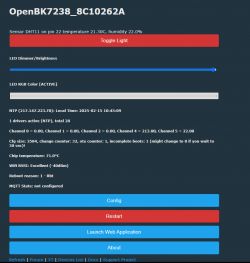
    This is a tiny temperature and in addition it is only shown for reference, it is not a precise measurement. For comparison, my dev board:
    OpenBK7238 user interface with temperature and humidity readings. .
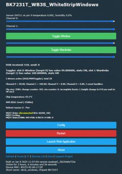
    My LEDs above the window:
    Screenshot of a user interface displaying BK7231T system parameters. .
    If you want to try to reduce the temperature and you are not using BL0937, you can try to autoexec.bat or to the startup command line add PowerSave 1 .
    Helpful post? Buy me a coffee.
  • #124 21440480
    EchoSin
    Level 9  
    >>21440305 .
    Thanks, you've cleared up my doubts.
    I care about the energy measurement, so I'll leave it as is.
    I may end up taping the housing already (maybe I'll try to add a screw or two).
  • #125 21451164
    Slash402
    Level 3  
    Hi everyone,
    I've been following this thread because I'm interested in flashing a smart plug that uses these chips. However, I'm quite new to this topic and would really appreciate some guidance.

    1. Which schematic should I follow to perform the flash? Should I connect to the T34 chip, or are the flashing pins also available on the BL0937?
    2. Is the 3V supply from the TTL-USB adapter sufficient, or do I need an external power source?
    3. Which specific firmware should I flash?

    Thanks in advance for any help!
  • #126 21451202
    rufus4
    Level 10  
    welcome,
    1. Go the way that suits you. If it does not work, choose another.
    2. This depends on the adapter. If it has a big capacitor, it could work. If not, better use an external power supply.
    3. Go with the newest, maybe visit the changelog to be informed about bigger changes.
  • #127 21451367
    Slash402
    Level 3  
    >>21451202
    1. I'd rather not, we're talking microsoldering here, I don't wanna go trial and error if people have already done and found the correct way before me. Also, that doesn't really answer my question regarding if the pins on the BL0937 can be used or not.
    2. This is the adapter that I have https://www.amazon.it/dp/B07TFSZ3ZP is there a way to tell if it's gonna work?
    3. Umm, I only know about this tool https://github.com/openshwprojects/BK7231GUIFlashTool and I'm not really sure what chip to select when flashing as none of the ones I have are listed?
  • #128 21451911
    max4elektroda
    Level 20  
    Slash402 wrote:
    >>21451202
    1. I'd rather not, we're talking microsoldering here, I don't wanna go trial and error if people have already done and found the correct way before me. Also, that doesn't really answer my question regarding if the pins on the BL0937 can be used or not.
    2. This is the adapter that I have https://www.amazon.it/dp/B07TFSZ3ZP is there a way to tell if it's gonna work?
    3. Umm, I only know about this tool https://github.com/openshwprojects/BK7231GUIFlashTool and I'm not really sure what chip to select when flashing as none of the ones I have are listed?

    Trying to answer your questions:

    If the layout of your T34 chip allows to access the pins with needles, you may try to adopt the solutions shown in this thread:
    https://www.elektroda.com/rtvforum/topic4051203.html
    The pins are not connected to the BL0937.

    Usually it's impossible to tell if a specific adapter works, but they usually do. I would advise to use a separate power supply in every case, but it might be sufficient to power the pins of the plug with a power supply, sometimes 12 to 15V is enough to start the plug without connecting to high voltage.

    T34 is the "BK7231N" chip.
  • ADVERTISEMENT
  • #129 21453078
    Slash402
    Level 3  
    Thanks, that clarified things quite a bit.

    max4elektroda wrote:
    Usually it's impossible to tell if a specific adapter works, but they usually do. I would advise to use a separate power supply in every case, but it might be sufficient to power the pins of the plug with a power supply, sometimes 12 to 15V is enough to start the plug without connecting to high voltage.

    I'm not quite sure about one thing: why do I need to supply 12/15V if the pin requires 3.3V? Wouldn't I risk damaging something by providing 12V?

    Also, I noticed that some people add a capacitor to the TTL. Why is that? Is there a guide I can read to understand how to do it? Unfortunately, I couldn't find much on the forum.
  • #130 21453241
    p.kaczmarek2
    Moderator Smart Home
    I think Max meant that you can connect 12V DC to the input of the plug directly. Not to the 3.3V rail, of course! That would burn WiFi module.

    Capacitor to TTL or to AMS1117-3.3V? If you mean the later, then answer is in the AMS1117 datasheet. It's recommended and required for stable voltage.
    Helpful post? Buy me a coffee.
  • ADVERTISEMENT
  • #131 21453273
    max4elektroda
    Level 20  
    p.kaczmarek2 wrote:
    connect 12V DC to the input of the plug directly. Not to the 3.3V rail

    Exactly, sorry if this was not clear.
    I have some plugs which works perfectly on 12V on the "high voltage input", the plugs contacts, usually plugged into the power outlet, some which obviously will need more voltage and won't start that way.
    As long as you have a decent 3.3V supply, use that.
  • #132 21454169
    Slash402
    Level 3  
    >>21453241
    p.kaczmarek2 wrote:
    I think Max meant that you can connect 12V DC to the input of the plug directly. Not to the 3.3V rail, of course! That would burn WiFi module.

    Oh I see. So instead of connecting to the 3V3 pin, I can just try to power the device using 12/15V?

    p.kaczmarek2 wrote:
    Capacitor to TTL or to AMS1117-3.3V? If you mean the latter, then answer is in the AMS1117 datasheet. It's recommended and required for stable voltage.

    I mean things like this I saw in the forum https://obrazki.elektroda.pl/6133912500_1714225565.png (capacitor attached to the TTL adapter).
  • #133 21523164
    Slash402
    Level 3  
    >>21454169
    Update. I managed to flash it fine, just by using the TTL adapter and nothing else.
    Just a couple of questions if anyone knows.
    1. Is it possible to set up a routine (eg. turn on at X time, turn off at Y time) that will keep working without being connected to a network?
    2. Is it possible to flash ESPHome via OTA in case I'd like to?
    Thanks.
  • #134 21584105
    spleefer90
    Level 7  
    I wish I had found this thread before doing everything - this is my working attempt, I held the 3v3 with my hand which came handy when I was resetting power.

    [T34/BL0937] Teardown Generic Wifi Smart Plug with Energy Measurement
    [T34/BL0937] Teardown Generic Wifi Smart Plug with Energy Measurement
  • #135 21622865
    Drakarah
    Level 5  
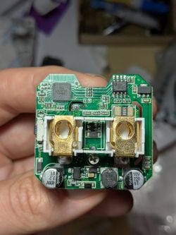
    I have a variant of this board (bought from https://nl.aliexpress.com/item/1005008591175083.html), which at first I thought was the board from https://www.elektroda.com/rtvforum/topic4099021.html but in green as the antenna layout is the same, but it comes with a BL0937 instead of a BL0942.

    A green PCB featuring a BL0937 chip, visible traces and pads, with some pins labeled.

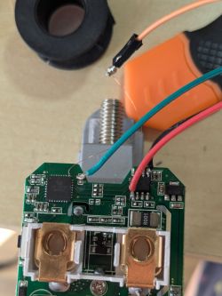
    The T34 has a different serial 244TGF187 but the pinout is the same, I confirmed 3.3v and GND with the pins on BL0937, and TX is also broken out to an unpopulated pad, which leaves RX being the hardest pin to tap into. I don't think that pin is used anywhere so I'll have to use the needle method or push my luck with trying to solder some enameled wire to a 0.2mm exposed area (I have never micro soldered before).

    Edit:
    To my own surprise I managed to solder the wires

    [T34/BL0937] Teardown Generic Wifi Smart Plug with Energy Measurement

    And was able to dump the firmware


    Edit2:

    Flashed succesfully and the config for the pins is working (https://www.elektroda.com/rtvforum/topic4042412.html#21030449). The wifi is really bad though, worse RSSI than other smart plugs on the same location.


    Edit3:

    It doesn't seem to like HA discovery, the moment it queues the HA discovery it warns about low heap memory and then ultimately reboots
    
    Info:MAIN:Time 44, idle 222630/s, free 62504, MQTT 1(1), bWifi 1, secondsWithNoPing -1, socks 2/38 
    Info:MQTT:MQTT client in mqtt_incoming_publish_cb topic TuyaSmartplug10/power_apparent/get
    Info:MQTT:MQTT client in mqtt_incoming_publish_cb topic TuyaSmartplug10/power_reactive/get
    Info:MAIN:Will do request HA discovery now.
    Info:HTTP:HASS counts: 1 rels, 0 pwms, 0 inps, 0 excluded
    Info:MQTT:MQTT client in mqtt_incoming_publish_cb topic TuyaSmartplug10/power_factor/get
    Info:MQTT:Queued topic=homeassistant/sensor/TuyaSmartPlug10_sensor_0/config, 1 items in queue
    Info:MQTT:Queued topic=homeassistant/sensor/TuyaSmartPlug10_sensor_138/config, 2 items in queue
    Info:MQTT:Queued topic=homeassistant/sensor/TuyaSmartPlug10_sensor_1/config, 3 items in queue
    Info:MQTT:Queued topic=homeassistant/sensor/TuyaSmartPlug10_sensor_2/config, 4 items in queue
    Info:MQTT:Queued topic=homeassistant/sensor/TuyaSmartPlug10_sensor_9/config, 5 items in queue
    Info:MQTT:Queued topic=homeassistant/sensor/TuyaSmartPlug10_sensor_10/config, 6 items in queue
    Info:MQTT:Queued topic=homeassistant/sensor/TuyaSmartPlug10_sensor_11/config, 7 items in queue
    Info:MQTT:Queued topic=homeassistant/sensor/TuyaSmartPlug10_sensor_3/config, 8 items in queue
    Info:MQTT:Queued topic=homeassistant/sensor/TuyaSmartPlug10_sensor_4/config, 9 items in queue
    Info:MQTT:Queued topic=homeassistant/sensor/TuyaSmartPlug10_sensor_7/config, 10 items in queue
    Info:MQTT:Queued topic=homeassistant/sensor/TuyaSmartPlug10_sensor_6/config, 11 items in queue
    Info:MQTT:Queued topic=homeassistant/sensor/TuyaSmartPlug10_sensor_12/config, 12 items in queue
    Info:MQTT:Queued topic=homeassistant/sensor/TuyaSmartPlug10_sensor_13/config, 13 items in queue
    Info:MQTT:Queued topic=homeassistant/sensor/TuyaSmartPlug10_sensor_8/config, 14 items in queue
    Info:MQTT:Queued topic=homeassistant/sensor/TuyaSmartPlug10_sensor_20/config, 15 items in queue
    Info:MQTT:Queued topic=homeassistant/sensor/TuyaSmartPlug10_sensor_21/config, 16 items in queue
    Info:MQTT:Queued topic=homeassistant/sensor/TuyaSmartPlug10_sensor_22/config, 17 items in queue
    Info:MQTT:Queued topic=homeassistant/sensor/TuyaSmartPlug10_sensor_23/config, 18 items in queue
    Info:MQTT:Queued topic=homeassistant/sensor/TuyaSmartPlug10_sensor_24/config, 19 items in queue
    Info:MQTT:Queued topic=homeassistant/switch/TuyaSmartPlug10_relay_0/config, 20 items in queue
    Info:MQTT:Queued topic=homeassistant/sensor/TuyaSmartPlug10_temp/config, 21 items in queue
    Info:MQTT:Queued topic=homeassistant/sensor/TuyaSmartPlug10_rssi/config, 22 items in queue
    Info:MQTT:Queued topic=homeassistant/sensor/TuyaSmartPlug10_uptime/config, 23 items in queue
    Info:MQTT:Queued topic=homeassistant/sensor/TuyaSmartPlug10_build/config, 24 items in queue
    Info:MQTT:Queued topic=homeassistant/sensor/TuyaSmartPlug10_ssid/config, 25 items in queue
    Info:MQTT:Queued topic=homeassistant/sensor/TuyaSmartPlug10_ip/config, 26 items in queue
    Info:MQTT:Publishing val (324 bytes) to homeassistant/sensor/TuyaSmartPlug10_sensor_0/config retain=1
    Info:MQTT:Publishing val (350 bytes) to homeassistant/sensor/TuyaSmartPlug10_sensor_138/config retain=1
    Info:MQTT:Publishing val (324 bytes) to homeassistant/sensor/TuyaSmartPlug10_sensor_1/config retain=1
    Error:MAIN:Low heap warning!
    

Topic summary

The discussion centers on the teardown, flashing, and firmware modification of generic WiFi smart plugs featuring the T34 chip with integrated energy measurement capabilities, primarily using the BL0937 or BL0942 power metering ICs. Users report challenges soldering to the T34 chip due to fragile pads and limited access to UART pins, with some resorting to desoldering the chip or using fine wires and needles to establish serial connections. Flashing is typically done via UART with external 3.3V power supplies to ensure stable operation, as USB-TTL adapters alone often lack sufficient current. The T34 chip is identified as BK7231N-based, treated either as a chip or board module in firmware configurations. Firmware flashing is performed using OpenBeken and BK7231Flasher tools, with users sharing pin mappings and configuration templates for BL0937 and BL0942 drivers. PowerSave mode behavior is discussed, with reports of inconsistent functionality in newer firmware versions. MQTT integration issues affecting relay startup states are resolved by resetting MQTT configurations and rediscovering devices in Home Assistant. The community shares detailed hardware photos, pinouts, and flashing procedures, emphasizing the need for precise soldering, proper power supply, and correct firmware settings to enable WiFi connectivity and power metering features. Variants of the smart plug with different power metering chips and PCB layouts are noted, with some devices requiring specific handling of UART lines routed through the BL0942 chip. Overall, the thread provides comprehensive technical guidance for hardware hacking, firmware flashing, and configuration of T34-based smart plugs with energy measurement.
Summary generated by the language model.
ADVERTISEMENT